AutoCAD 2015: Text Align Dynamically

A new feature in AutoCAD 2015 is the Text Align tool found on the “Annotate” tab > “Text” Panel and the button that has 2 stacked letter A’s. The command to start this command is TEXTALIGN <enter> and the command alias is TA <enter>TextAlign1


This command works on both MTEXT and DTEXT (single line text) and makes the process of aligning text easy.

(side note: I refer to single line text as “DTEXT” because that is how AutoCAD refers to that type of text.

  • The alias to quickly add DTEXT is simply DT <enter>.
  • The alias to quickly add MTEXT is T <enter>…)

By default, this command uses a text object’s insertion point based on how it it is justified. Below is a selection set of both MTEXT and DTEXT showing the grips of their insertion points.

TextAlign3

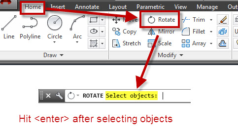
You are then prompted to Select a Text object.
The text object that you select will define the first point of alignment by its insertion point

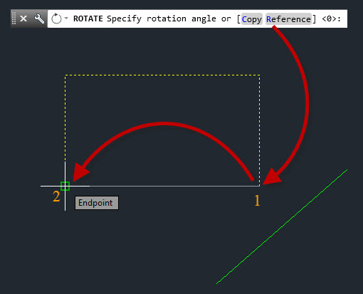
after you select the text, the alignment can be at any angle. The picture below shows the text being aligned without ORTHO turned OFF and the angle of the cursor is at some random angle…

TextAlign4

The picture below shows how the text will look when ORTHO is turned ON and the cursor is pulled up (or down will work as well).

TextAlign5 ortho


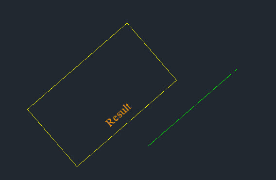
Below is the result of the aligned text.

TextAlign6 Result

TextAlign Select text

As a good AutoCAD user I hope that you noticed that during the command, there are options. All of the options are helpful but one of them stands out. This is the “Distribute” option.

Distribute Option: This option aligns the text and evenly spaces (distributes) them between 2 points.

The steps shown below are:

  • TA <enter> to start the TEXTALIGN command
  • Select the text objects to be aligned <enter>
  • P <enter> to start the “Points” sub-option
  • Pick the first point (upper line)
  • O <enter> to start the “Options” sub-menu
  • D <enter> to select “Distribute”
  • Pick Second point (lower line)

TextAlign Distribute


Make sure to check out this AutoCAD help link for more helpful info about the features of this command: http://help.autodesk.com/view/ACD/2015/ENU/?guid=GUID-CC1BE498-4908-434E-8FDA-0DE87E05EA15

Posted in AutoCAD 2015, Modifying, New in 2015, Text | Tagged | 5 Comments

AutoCAD Cursor/Crosshair Angle

Have you ever opened someone else’s drawing and the AutoCAD cursor is at some odd angle?

The system variable to help control this setting is SNAPANG.

Below is an example of a cursor at an odd angle while in a layout tab

odd cursor angle

odd cursor angle

A quick glance at the system variable description doesn’t seem to be all that clear, but I know that if I enter SNAPANG in the commandline, it will make more sense.

SNAPANG 2

SNAPANG 3


Side note: There are a few “common courtesy” or “drawing etiquette” rules that I wish more people would follow when they exit a drawing. This topic is worthy of its own blog post and I will put one together in the future. But the idea is that before closing a drawing, make the drawing so that the file is optimized for the next guy.

This includes, setting the USC to World, Zoom to a view that isn’t confusing or change to a LAYOUT tab and zoom to the titleblock for the next guy, AUDIT the drawing to fix any errors. Check the SNAPANG and set it to zero…


Posted in BASICS, TIPS | 1 Comment

AutoLISP: Change Text Styles

Today’s featured routine was posted by “Peter” at Augi.com found here: http://forums.augi.com/showthread.php?22959-Help-Changing-text-style-in-blocks

This routine helps changes the text style of text objects and even attributes inside of blocks to a user specified text style. This is helpful for when you receive drawings from another source and would like to change text styles to match your text styles.

For this routine to work, the desired text style must exist in the drawing.

The format of how to run this routine is different than other routines that you might be used to. You load the lisp routine as normal, but there isn’t a command that you enter at the commandline. What you do is pass feed the LISP routine the “function” that runs the routine and then the 2 variables in order for it to run.

The format that you feed the command line is:
(changestyle “oldtextstylename” “newtextstylename”)

changestyle = starts the function (starts the routine)
oldtextstylename = replace this text with the name of the text style that you would like to be replaced. Note – keep the name in “quotes”
newtextstylename = replace this text with the name of the text style that you would like to replace the previous style. Note – keep the name in “quotes”

Text Style Change


;;; Changes objects that are set to one text style to another text style. Both styles need to be defined in the drawing.
;;; Posted by Peter
;;; http://forums.augi.com/showthread.php?22959-Help-Changing-text-style-in-blocks
;;;
;;; Use the foloowing format in the command line after loading the routine:
;;; (changestyle "oldtextstylename" "newtextstylename")
;;; 
(defun ChangeStyle (strStyle1 strStyle2 / entItem objBlock objDocument objItem )
 (vl-load-com)
 (setq objDocument (vla-get-activedocument (vlax-get-acad-object)))
 (if (and (tblobjname "style" strStyle1)
          (tblobjname "style" strStyle2)         
     )
  (vlax-for objBlock (vla-get-blocks objDocument)
   (if (> (vla-get-count objBlock) 0)
    (progn
     (setq objItem (vla-item objBlock 0)
           entItem (vlax-vla-object->ename objItem)
     )
     (while entItem
      (if (and (vlax-property-available-p (setq objItem (vlax-ename->vla-object entItem)) "StyleName")
               (= (strcase (vla-get-stylename objItem)) (strcase strStyle1))
          )
       (vla-put-stylename objItem strStyle2)
      )
      (setq entItem (entnext entItem))
     )
    )
   )
  )
  (princ "\nError check if styles exist: ")
 )
 (vla-regen objDocument 0)
)

Text Style Merge 1


Text Style Merge 2

Posted in AutoLISP, AutoLISP: Attributes, AutoLISP: Manage, AutoLISP: Text | 9 Comments

AutoLISP: Rotate Multiple Objects Around Their Base Point

There are 2 things in this blog post that I want to point out.

1) Share a LISP routine that rotates multiple objects around their individual base points…

2) The lisp routine shown in this post hasn’t been altered since 1991 and it still works in AutoCAD 2014. This may not seem like a big deal but with all of the various programming languages available to be used within AutoCAD, the power of using a LISP routine that hasn’t had to be changed or updated in over 20 years is pretty impressive.

Rotate Multiple Lisp routine with date shown

Rotate Multiple Lisp routine with date shown

The Routine allows you to rotate multiple objects such as blocks and text objects that have an “Insertion Point”  to a user-specified angle. And instead o0f rotating everything around one base point, the object’s individual base point is used.

In the example below, there is a vertical column of blocks that are rotated clockwise by 90s. I don’t know why, but all that I know is that I want them right-side-up.

Rotate Multiple

Here’s how:

  • Load the routine
  • ROTMULT <enter> to start
  • Select objects
  • <enter> when finished selecting
  • “Enter Rotation Angle:” enter a positive number to rotate the objects counter-clockwise (example 90) and a negative number to rotate the objects clockwise (example -90)

~Enjoy


;* Rotate Multiple
;* Rotates many entities around their respective basepoints
;* allows selection by AUTOCAD selection sets or SSX.
;* Written by David Husch, January 1991

(defun c:rotmult ()
  (prompt "Select Entities to Rotate, <ENTER> for SSX.")
  (setq ss (ssget))
  (if (not ss) (setq ss (ssx)))
  (setq num (sslength ss))
  (setq x 0)
  (if ss 
  	(if (setq ang (getreal "Enter Rotation Angle: "))
	  	(repeat num
		  	(setq ename (ssname ss x))
		    (setq elist (entget ename))
			(setq pnt (cdr(assoc 10 elist)))
			(command "Rotate" ename "" pnt ang)
 		    (setq x (1+ x))
	    	)
	  	)
    )
  )

Posted in AutoLISP, AutoLISP: Blocks, AutoLISP: Modify, AutoLISP: Text | 34 Comments

XREF Load Status App Review

The app mentioned in this post saved my sanity while opening drawings that contained a large amount of XREFs (External References). The “XREF Load Status” app is available from the Autodesk Exchange Apps store in a free version that will only work with XREFs that are .dwg files or a paid version that will work with XREFs that .dwg, .DGN and various image files. I spent the $5 for the full version since I knew that I would be dealing with various file types from time to time. I usually don’t do a review like this but this app needs deserves it.

The app is made by RedTransit Consultants. They have other apps available and also services to develop custom apps as well.

The project that I used this app on had a ridiculous amount of XREFs some of which were huge. Some files referenced over 140 other files and the disk size was well over 350 megabytes and it took multiple minutes to open. And the thing is that maybe the only edit that was needed to be made was a text edit or Attribute edit.

That’s where this app came in to save the day.

Shown below is a well known file that contains multiple XREFs. Lets say you wanted to be able to control which XREFs will open when you open your file. With this app you can control this – it could be a few XREFs or none…

XRLS 1


After installing the XREF Load Status APP, it should appear under the “Plugins” tab of the ribbon. Click to start.

Note that you should launch the app from another drawing or in a blank drawing. Basically, you are controlling the XREFs in a drawing without being in that drawing…

XRLS 2

Once the tool starts, you will see the dialog box shown below.
Click the long button  that says “Select Drawing File to Open…

XRLS 3

Navigate to the file and select it and click open:

XRLS 4

The drawing’s XREFs will display in the dialog box and the various option of how the XREFs are loaded will be shown.

Note that the current “Load Status” is shown under the corresponding sides of the dialog box. Files in the left column are not currently loaded (UNLOADED) and the files in the right side are currently loaded

There are a few choices to help you select which XREFs are loaded or unloaded:

  • Sort Ascending – will sort the list of XREFs in alphabetical order
  • Check All – will check all of the check-boxes in the list
  • Clear All – unchecks all of the check-boxes in the list
  • Invert All Toggles – Will let you easily switch the checks in the check-boxes. This is great becasue otherwise you would have to use the select all button and then go through and deselect the XREFs that you want loaded. So – to use this option, you go through the list of XREFs and check the ones that you want loaded and then click this button to “invert” those selections.

Once you have made your selections, you are given the choice of what to do with these changes, You can simply save these setting in that file without opening it and move on to the next one, or you can apply these settings and open the file.

XRLS 5


Shown below is a list of the XREFs that are “Unloaded”

XRLS 7

The drawing shown below is the file with all of the XREFs not being loaded upon opening.

XRLS 8


~enjoy

Posted in Customization, XREFs | Leave a comment

AutoLISP: Closed Objects to Wipeout updated

It has been a while since using this LISP routine, but apparently the routine that was posted a couple of years ago (found here: https://autocadtips.wordpress.com/2011/05/28/autolisp-objects-2-wipeout/) and written by Giles Chanteau stopped working in newer releases of AutoCAD because it now needs to call upon a different .ARX file (AutoCAD Runtime eXtension).

OB2WO 3

The LISP routine creates a wipeout object from selecting a closed object. This might not seem like a big deal since you can do the same thing with the WIPEOUT command, but this routine lets you select closed curved objects with the exception of SPLINE objects.

Here’s how:

  • Load the code below
  • Use OB2WO <enter> in the command line to start.
  • Select  a closed object whose shape from which you would like to create a wipeout (Circle, Ellipse, Closed Polyline with or without arc segments).

OB2WO 4

  • After selecting the object, you are asked if the object that you selected should be erased after the wipeout is created. By default, “No” is selected and the object will remain and the wipeout that is created is placed on the current layer. so make sure that the layer you want it on is set current,
Hatch with various shapes covering the hatch

Hatch with various shapes covering the hatch

The above picture shows a Hatched area with some curved closed shapes.

Shown below, The wipeouts have been created and the original selected object remains.

OB2WO 2


Thanks to Giles Chanteau for his routines and for his presence on the various forums always willing to ask and answer question in a pleasant manner, Thanks again Giles

~Greg


;;; OB2WO (gile) -Gilles Chanteau- 10/03/07
;;; Creates a "Wipeout" from an object (circle, ellipse, or polyline with arcs)
;;; Works whatever the current ucs and object OCS
;;; http://forums.autodesk.com/t5/Visual-LISP-AutoLISP-and-General/wipeout-with-arcs/m-p/786490#M12148

(defun c:ob2wo (/ ent lst nor)
  (vl-load-com)
  (if (and (setq ent (car (entsel)))
	   (member (cdr (assoc 0 (entget ent)))
		   '("CIRCLE" "ELLIPSE" "LWPOLYLINE")
	   )
	   (setq lst (ent2ptlst ent))
	   (setq nor (cdr (assoc 210 (entget ent))))
      )
    (progn
      (vla-StartundoMark
	(vla-get-ActiveDocument (vlax-get-acad-object))
      )
      (makeWipeout lst nor)
      (initget "Yes No")
      (if
	(= (getkword "\nDelete source object? [Yes/No] <No>: ")
	   "Yes"
	)
	 (entdel ent)
      )
      (vla-EndundoMark
	(vla-get-ActiveDocument (vlax-get-acad-object))
      )
    )
  )
)


;;; ENT2PTLST
;;; Returns the vertices list of the polygon figuring the curve object
;;; Coordinates defined in OCS

(defun ent2ptlst (ent / obj dist n lst p_lst prec)
  (vl-load-com)
  (if (= (type ent) 'ENAME)
    (setq obj (vlax-ename->vla-object ent))
  )
  (cond
    ((member (cdr (assoc 0 (entget ent))) '("CIRCLE" "ELLIPSE"))
     (setq dist	(/ (vlax-curve-getDistAtParam
		     obj
		     (vlax-curve-getEndParam obj)
		   )
		   50
		)
	   n	0
     )
     (repeat 50
       (setq
	 lst
	  (cons
	    (trans
	      (vlax-curve-getPointAtDist obj (* dist (setq n (1+ n))))
	      0
	      (vlax-get obj 'Normal)
	    )
	    lst
	  )
       )
     )
    )
    (T
     (setq p_lst (vl-remove-if-not
		   '(lambda (x)
		      (or (= (car x) 10)
			  (= (car x) 42)
		      )
		    )
		   (entget ent)
		 )
     )
     (while p_lst
       (setq
	 lst
	  (cons
	    (append (cdr (assoc 10 p_lst))
		    (list (cdr (assoc 38 (entget ent))))
	    )
	    lst
	  )
       )
       (if (/= 0 (cdadr p_lst))
	 (progn
	   (setq prec (1+ (fix (* 25 (sqrt (abs (cdadr p_lst))))))
		 dist (/ (- (if	(cdaddr p_lst)
			      (vlax-curve-getDistAtPoint
				obj
				(trans (cdaddr p_lst) ent 0)
			      )
			      (vlax-curve-getDistAtParam
				obj
				(vlax-curve-getEndParam obj)
			      )
			    )
			    (vlax-curve-getDistAtPoint
			      obj
			      (trans (cdar p_lst) ent 0)
			    )
			 )
			 prec
		      )
		 n    0
	   )
	   (repeat (1- prec)
	     (setq
	       lst (cons
		     (trans
		       (vlax-curve-getPointAtDist
			 obj
			 (+ (vlax-curve-getDistAtPoint
			      obj
			      (trans (cdar p_lst) ent 0)
			    )
			    (* dist (setq n (1+ n)))
			 )
		       )
		       0
		       ent
		     )
		     lst
		   )
	     )
	   )
	 )
       )
       (setq p_lst (cddr p_lst))
     )
    )
  )
  lst
)


;;; MakeWipeout creates a "wipeout" from a points list and the normal vector of the object

(defun MakeWipeout (pt_lst nor / dxf10 max_dist cen dxf_14)
  (if (not (member "acismui.arx" (arx)))
    (arxload "acismui.arx")
  )
  (setq	dxf10 (list (apply 'min (mapcar 'car pt_lst))
		    (apply 'min (mapcar 'cadr pt_lst))
		    (caddar pt_lst)
	      )
  )
  (setq
    max_dist
     (float
       (apply 'max
	      (mapcar '- (apply 'mapcar (cons 'max pt_lst)) dxf10)
       )
     )
  )
  (setq cen (mapcar '+ dxf10 (list (/ max_dist 2) (/ max_dist 2) 0.0)))
  (setq
    dxf14 (mapcar
	    '(lambda (p)
	       (mapcar '/
		       (mapcar '- p cen)
		       (list max_dist (- max_dist) 1.0)
	       )
	     )
	    pt_lst
	  )
  )
  (setq dxf14 (reverse (cons (car dxf14) (reverse dxf14))))
  (entmake (append (list '(0 . "WIPEOUT")
			 '(100 . "AcDbEntity")
			 '(100 . "AcDbWipeout")
			 '(90 . 0)
			 (cons 10 (trans dxf10 nor 0))
			 (cons 11 (trans (list max_dist 0.0 0.0) nor 0))
			 (cons 12 (trans (list 0.0 max_dist 0.0) nor 0))
			 '(13 1.0 1.0 0.0)
			 '(70 . 7)
			 '(280 . 1)
			 '(71 . 2)
			 (cons 91 (length dxf14))
		   )
		   (mapcar '(lambda (p) (cons 14 p)) dxf14)
	   )
  )
)
Posted in AutoLISP: Creating, AutoLISP: Modify, AutoLISP: Polylines, Wipeouts | 11 Comments

Missing Hatch Ribbon or Dialog Box setting

Hatch Ribbon 1The hatch ribbon has become the “norm” for the last couple of releases of AutoCAD but you may have switch how you place and edit hatches to the legacy dialog box version. But what happens if you switch to the dialog box version and then want the Hatch “contextual ribbon” back?

Tip: a “Contextual Ribbon” is a ribbon tab that appears only when a particular command is being used or particular object. Another example of a Contextual Ribbon tab is while placing MTEXT (Use the alias T <enter> to place MTEXT…)

Tip 2: From within the Hatch contextual ribbon, you can open the Hatch dialog box by clicking the diagonal arrow in the “Options” panel (shown below)

Hatch Dialog 2


The system variable that controls which version (ribbon or dialog box) is HPDLGMODE (shown below).

The out-of-the-box setting which displays the contextual ribbon is <2>


Out of the box Hatch ribbon 1


~enjoy

Posted in BASICS, Hatch | 2 Comments

Rotate Objects to Reference an Angle

The Rotate command can be used to match an angle of an existing object or allow you to input an angle.

Rotate_Reference_1


This tip is especially helpful when you don’t know the angle of the objects. maybe all you know is that the objects need to be rotated to match something else…

Here’s how:

Start the ROTATE command.
The alias to start the command is RO <enter>

Rotate_Reference_2

Select The objects that need to be rotated.

Hit <enter> when finished

Tip: You can Start the Rotate command from the right-click menu. Simply select the objects and then right-click and select “Rotate” Also note the other command that are available from this menu.

Rotate_Reference_1a

Specify the base point for the rotation. The base point is the pivot point that the objects will rotate around.

Rotate_Reference_3


Use the sub-option “Reference” of the command by either selecting the blue R in the command line or by using R <enter>

Then pick 2 points to define the angle of the objects. This angle will match the angle in the next step.


Rotate_Reference_6

Use the sub-option “Points” by clicking the blue P or by using P <enter> in the command line.

Pick 2 points to define the angle for the rotated objects.

Note: The order of the picked points from the “Reference” option will match the order of the “Points” option of the command.

Rotate_Reference_4


The result will be similar as shown below:

Rotate_Reference_5


Tip: The hot-grip method of the “Rotate” command does not have the “Points” sub-option of the command so it will help have the same result.

Just in case you don’t know how to start the hot-grip method:
The hot grip method lets you start some command without entering a command. You simply select the objects and then click on any grip. Notice how it becomes red? This is a “hot-grip.” Now if you right click, you see a limited (and different) right click menu. You can start other command from this menu.

Rotate_Reference_1b

Posted in BASICS, Modifying, TIPS | 12 Comments

AutoLISP: Convert 2D Solid to Polyline Outline

Since 2D solids aren’t very friendly after you place them and are hard to edit, you may need find this tool helpful for converting the solid into a polyline that represents the outline of the solid.

An example of its use is editing existing drawings… I have been adjusting blocks from an older block library where some parts of the blocks contain “arrowheads” but they are really just 2D solids. This is helpful so that the users don’t actually snap to these arrows. But a few of them no longer conform to our new CAD standards and sadly, some of the geometry was drawn incorrectly. So I have been using this routine to adjust these stubborn objects.

Here’s how:

  • OUTLINESOLID <enter>
  • Select the 2D Solid
Convert 2D Solid to Polyline

Convert 2D Solid to Polyline


;;; Select a 2D solid and this will delete the solid and replace its outline with a polyline
;;; http://forums.autodesk.com/t5/Visual-LISP-AutoLISP-and-General/Solid-object-to-Polyline/td-p/783079
;;; Posted By: Schamenek, Alex
(defun c:outlinesolid(/ solid pt1 pt2 pt3 pt4)
   (prompt "\nPlease select the solid you want to outline.")
   (WHILE (NOT (setq solid (ssget ":S" '((0 . "SOLID")))))
      (prompt "\nPlease select the solid you want to outline."))
      (SETQ pt1 (cdr (assoc 10 (entget (ssname solid 0))))
         pt2 (cdr (assoc 11 (entget (ssname solid 0))))
         pt3 (cdr (assoc 12 (entget (ssname solid 0))))
         pt4 (cdr (assoc 13 (entget (ssname solid 0))))
       );SETQ
   (COMMAND "_.PLINE" PT1 PT2 PT4 PT3 "C")
   (command ".erase" solid "")
);DEFUN
Posted in AutoLISP, AutoLISP: Modify, AutoLISP: Polylines | 8 Comments

View Fonts Used in Styles Without Opening A Drawing

Continuing the previous blog post concerning how to control what font is being used as the “Standard” text style – One issue that has come up is that upon opening a drawing that has the “Standard” text style defined as something other than what your machine has it set as, the text in the drawing is being changed  before the user has any control over it. Therefore they might not even know what the initial font was set as when the drawing was sent to them.

One way to check this is to use the Reference Manager tool that installs with AutoCAD.

This tool lets you see what a file’s needed references are and repath them if they are located in a different location without opening the file. (XREFs, .ctb files, Printer Configuration files [.pc3] fonts…

Here’s how:

Open the Reference Manager tool

Start > All Programs > Autodesk >  AutoCAD (version) > Refernce Manager

Opening the Reference Manager

Opening the Reference Manager

Upon opening, You are prompted to load all references (nested) or only the top level of references. If all you want to see is the drawing in question and it doesn’t have any references, use the bottom option.

Reference Manager Prompt

Reference Manager Prompt

When the Reference Manager loads – Simply “Add Drawings” and navigate to the drawing you need more information about. After “adding” the drawing. Notice that the font and the corresponding Text Style are shown. Simply jot this down and you now know what font goes with what Style.

Reference Manager for Text Style Fonts 2


Posted in Customization, Manage, Text, TIPS | 2 Comments