Change the “Standard” Font in AutoCAD Template

Some drafting standards require a text “font” that is something other than the “Arial” font, yet AutoCAD seems to keep reverting back to this font even after changing what font the text style is using. Some people almost have conniption fits because their text keeps changing…

Shown below: “Standard” text style using Arial.ttf

Standard Style using Arial.ttf

Standard Style using Arial.ttf

One reason is that the default acad.dwt  that is used for new drawings has this font defined for the “Standard” style. My first suggestion would be to not use a style named “Standard” as this can cause obvious conflicts. But even if you have no control over this, you can try the following:

Navigate to your AutoCAD Template folder and locate the “acad.dwt” file – The below screen shot is of the AutoCAD 2014 template folder.

AutoCAD 2014 Template location

AutoCAD 2014 Template location

Copy the file to another location as a back up in case something goes wrong.

Rename the file so that it is “acad.dwg” not a “.dwt” file

change file type to .dwg

change file type to .dwg

Open the in AutoCAD and change the Text Style in the “Text Style Manager” by using the command ST <enter>

Change the “Standard” style to the desired font under the “Font Name:” dropdown list.

Standard Style Set to "RomanS.shx"

Standard Style Set to “RomanS.shx”

  • Save and close the drawing. Note: Prior to closing, you may want to “SAVEAS” to an earlier version so that other AutoCAD users that use older version of AutoCAD can use this same file.
  • Change the file type from .dwg to .dwt so that it is once again a template file
  • Place the “acad.dwt” file back in the support folder.
Posted in Customization, Manage, Text, TIPS | 13 Comments

AutoCAD Self Adjusting Text Frame Using Multileaders

If you have ever had to add a frame around your text and then have had to edit that text and re-adjust or even recreate the frame, today’s tip will help save you the time from having to edit both the text and frame by simply editing the text.

The following tip has been tested successfully with AutoCAD 2013 and 2014. AutoCAD 2011 doesn’t have the controls to make this tip work as easily and adjustable and I don’t have a way to test this tip in AutoCAD 2012.

MLEADER TEXT BOX 1

Tip: after placing the multileader, adjust the width of the text column since multileaders width are collapsed…

MLEADER TEXT BOX 3

The first thing needed is to set up a multileader “Style” that has the desired text style and height defined

Open the MultiLeader style dialog by entering MLS <enter> in the command line or by clicking on the diagonal arrow in the bottom right of the “Leaders” oanel of the “Annotate” ribbon.

MLEADER TEXT BOX 2

Set the desired text style and heights to your new multileader style and make sure to apply the check mark next to “Frame text” under the “Content” tab. This applies the frame around your text that automatically adjusts.

MLEADER TEXT BOX 4

Apply the Multileader style to the desired multileaders. Notice that there is now a frame around the text. But also notice that there is a leader attached…

MLEADER TEXT BOX 5

To remove the leader:

  • Select the Multileader
  • Hover over the arrow endpoint of the Multileader
  • Select “Remove Leader”

MLEADER TEXT BOX 6

Enjoy your new auto-adjusting text box…

MLEADER TEXT BOX 7

Note: the size of the gap from the text to the frame is controlled by the “Landing gap” setting found in the “Content” tab of the Multileader “Style”

MLEADER TEXT BOX 8


Adding Background Mask to Hide background Objects:

  • Double click inside of the Multileader to activate the “Text Editor” contextual ribbon tab.
  • Click the “Background Mask” button that is found on the “Formatting” panel of the ribbon
  • In the Background Mask” dialog box, check the mark next to “Use background mask”
  • Also notice that the offset distance of the background mask is controlled from this dialog box.

Adding Background Mask To HideMLEADER Text Mask Done

Posted in Leaders, Text, TIPS, Uncategorized | 20 Comments

Raster Design Quick Start

A very cool AutoCAD add-on called “Raster Design” lets you easily incorporate raster images like .jpegs and .tif files in you drawing. The cool part about this software is that it lets you edits the images even though they are pixelated images. You can even convert these pixels into AutoCAD entities for editing using you normal AutoCAD commands and then when you need to present the edits in a PDF, you can change the AutoCAD entities back into the pixelated form so that they match the rest of the image.

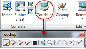
Shown below is the Raster Design 2014 ribbon tab:

Raster Design 2014 Ribbon Tab

Raster Design 2014 Ribbon Tab

Let’s get started:

  • INSERT AN IMAGE – Using the “Insert…” tool located on the far left of the ribbon, you can navigate to the image that is to be brought into the drawing. The command line version for this tool is IINSERT <enter>

Note: The terminology is a little confusing because usually images are brought into AutoCAD with the ATTACH command and blocks are usually the only things that are “inserted”…

IINSERT 1


  • Browse to the image.

Notice the options at the bottom of the screen. The 2 shown below are asking how you want to be prompted for various settings while inserting the image. If you want to take the default settings, click “Quick Insert”

INSERT IMAGE DIALOG 1


Once the image is in your drawing, you may need to re-position and scale the image to fit your needs. You can scale it by using the SCALE command or by dragging one of its corners to shrink or expand the image. To move the image, use the MOVE command.

IMAGE TO BITONAL – Many of the tools in Raster Design only work if the image is “bitonal” (black & white). Shades of grey or color images simply wont work well in Raster Design. To make the image “bitonal” click on the “Process Image” drop-down > then click “Change Color Depth” > then B <enter> in the command line to choose the “Bitonal” option.

IMAGE TO BITONAL


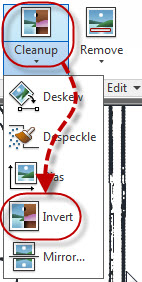
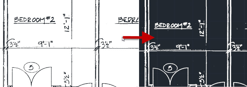
INVERT COLORS – Now that the image is in your drawing in black & white, you can change the colors so that you are working in a more familiar color scheme. You can easily invert the colors so that the lines are white and the background is your normal AutoCAD background.

Click on the “Cleanup” drop-down > then click “Invert”

IMAGE INVERT COLORS 1


(shown below: image colors inverted)

IMAGE INVERT COLORS 2


DESPECKLE – The little speckles that are present in the drawing from the image can be easily cleaned up and make your editing look that much cleaner (and easier to edit).

Click the “Cleanup” drop-down and then “Despeckle”

DESPCKLE 1


You are then asked to specify an area of the image that you wish to clean up. For this example I used I <enter> to clean the entire image.

Note: I did notice that on a few drawings, it erased some periods and commas in text that was in the image. So be aware that those may come across as “speckles” and may be cleaned.

DESPECKLE 2


You are then asked to specify the size of the speckle so that it will look for similar sized speckles and clean them up. You can do this by either picking within a speckle or by making a window selection. when you are done, the similar sized speckles that are found are highlighted in red and you are prompted to accept the selection set of what it is about to clean up.

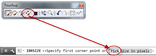
MANUAL TOUCH UP – You may need to manually touch up the drawing. For this, the “Touchup” tool allows you to manually erase or draw sections of the image similar to Microsoft Paint allows you to draw with a few pixels at a time.

TOUCHUP1

  • Toggle the color of the “Touchup” tool to either black or white by clicking  “Toggle drawing color”
  • The shape of the brush can be defined by the tools on the left side of the tool bar.
  • The angle of the brush is also defined on the 3rd tool from the left
  • The size of the brush can be changed by clicking the button shown below. This will let you define the size by either dragging a window or by entering a number.

TOUCHUP BRUSH SIZE 1


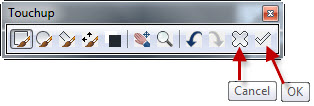
To exit the Touchup tool, use the buttons on the toolbar to CANCEL or OK to accept the edits.

Exit Touchup tool


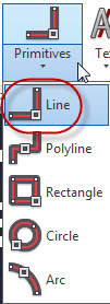
CONVERT PIXELATED LINES TO VECTOR LINES – This allows you to make edits with your familiar AutoCAD commands. In the example below I only show how to use the tool that recognizes lines. There are other tools that recognize arcs, circles, polylines and rectangles.

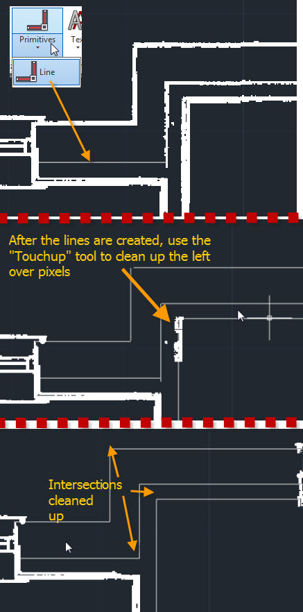
On the “Vectorize & Recognize Text” panel, click the “Primitives” drop-down and then select “Line”

Vecortize Lines


  • Place the cursor within a line in the image. If the line is recognized, a dashed line will appear that has a little yellow arrow (glyph). To accept this, hit <enter> and the pixelated line will be turned into an AutoCAD line and the pixelated line will be erased.

RASTER LINE CLEANUP


When using this to recognize lines that should meet at their corners, it may not work as precisely as you’d like, but you can clean them up by using FILLET with a ZERO radius.

You may also need to use the Touchup tool to clean up left over pixels…

Raster Line Cleanup 2


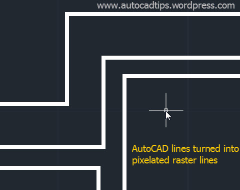
Once the edits have been made, you will need to plot the drawing but the AutoCAD lines will look so different from the rest of the image. To change the AutoCAD lines back into “Raster” simply select the AutoCAD objects and then right click > select “Merge Vector To Raster Image”

Vector to Ratser 1


The AutoCAD objects will now match the Raster objects in the image

Vector to Raster 2


MANAGING THE IMAGE FILE (EMBED) – When you bring an image into a drawing, AutoCAD treats the image as a reference. that means that there will be 2 files needed in order for someone else to see the same thing that you see. Luckily, you can easily embed the image so that it is in the .dwg file so you only need to send someone the one file.

On the “Insert & Write” panel, click the “EMBED” tool and in one click, the image is now embedded in your drawing.

Embed the Picture into the drawing

Posted in Raster Design | 32 Comments

AutoLISP: Print All Layout Tabs

Here is a simple routine that should help plot all of the layout tabs in a drawing.

Note: This routine will print all of the layouts with the same setups -so this is a limitation and shouldn’t be applied to drawings that have layout tabs with various sizes and or orientation (Landscape and Portrait).

Last tested and used with AutoCAD 2011.

~Greg


;; Prints All Layout Tabs and names the new PDFs with the name of the
;; drawing followed by the layout tab name.
;;
;; Adjust the paper size and .ctb file as needed.
;;
;; The PDFs will be placed in the folder where the drawing resides
;;
(defun c:PA ()
(foreach lay (layoutlist)
  (setvar 'CTab lay)
  (COMMAND 	"-PLOT"
		"Y"
		""
		"DWG To PDF.pc3"
		"ANSI full bleed A (8.50 x 11.00 Inches)"
		"Inches"
		"PORTRAIT"
		"N"
		"E"
		"f"
		"C"
		"Y"
		"monochrome.ctb"
		"Y"
		"N"
		"N"
		"N"
		""; Name of file
		"N"
		"y"      )
    )
)
Posted in AutoLISP, Printing - Plotting | 5 Comments

Express Tool: Save All Opened Drawings

If you have multiple drawings opened in AutoCAD at the same time and would like to save all the drawings before stepping away from your computer… you can easily save all the currently open drawings with one command.

Note: If there happens to be an unnamed drawing opened (like drawing1), you will prompted to give that file a name.

Here’s how:

  • SAVEALL <enter>

That’s it.

This command is an Express Tool so AutoCAD LT users will not be able to use this command.

I think that this tool should be a part of AutoCAD and not an Express Tool.

Multiple Drawings Open 1

Express Tool: Save All Opened Drawings

Posted in Express Tools, Manage | 7 Comments

Add Dimension Leader Line

Sometimes when placing dimensions in a drawing, they can get cluttered and it isn’t always clear what dimension text belongs to what dimension.

(pictured below – example dimension)

Add Leader Line 1

There is a feature that lets you attach a leader to the dimension text and the mid point of the dimension line thus pointing out what text is referring to what dimension.

Note: This method is should keep you from exploding dimensions. Please stop exploding dimensions!!!!

Here’s how:

  • Select the dimension that is to have the leader applied
  • Hover over the grip next to the dimension text
  • Select “Move with Leader”

Add Leader Line 2

The Leader will now follow the text as it is re-positioned away from the original text position.

Add Leader Line 3

If the leader is not needed, remove it by doing the following:

  • Select the dimension (similar to above)
  • Hover over the grip next to the dimension text
  • Select “Reset Text Position” – this will return the text to its original position. If you want move the text and get rid of the leader (without returning the text to the original position) select “Move Text Only.”

Add leader Line 4

Posted in Dimensions, Modifying, Text | 4 Comments

Continue A Table In A New Column With A Table Break

AutoCAD table objects are great in how they act similar to Microsoft Excel allowing you to add columns and rows and with the controls available, you can format the table in many ways to add style to the table.
Today’s tip is useful for tables that are long in length. If the table is long in length and you scale it to fit on a sheet in order to print, everything might be too small and run together, thus making your print unreadable.

Below is a simple example of an AutoCAD table (note: it isn’t a very long table…)

Table Break 1


To get the table to “break” and have a continuation:

  • Select the Table
  • Click the arrow grip at the bottom-middle of the table

Table Break 2


Click to re-position the arrow grip somewhere higher on the screen (within the table). You should see the table overflow into new columns to the right.

Table Break 3


The distance that you defined by re-positioning the arrow will be the new length for this table. So as new rows are added to the table, once the table reaches that defined length it will overflow once more into a third column.

Displaying The Labels In The Table Breaks:

Once these table breaks have been applied, you can add the descriptive top area of the table that is shown in the first rows of the table. This will help clarify what the second column is in the third table break for instance.

The first 2 rows of the table are called “Labels” and can be designated as a “Header” or “Title.” (These are defined in the Table Style manager). The important thing to know is that if both a “Title” and “Header” are defined, they are BOTH considered a label and will be repeated.

Table default content


To turn on the repeating labels:

  • Select the Table
  • Right-Click and select “Properties” to open the properties palette

Table Break 4'


  • In the properties palette, scroll down to the “Table Breaks” section
  • Change “Enabled” to “Yes”
  • Change “Repeat top labels” to “Yes”
  • The result should be a repeated “Label” in the Table Breaks

Table Break 5

Posted in Modifying, Tables | 3 Comments

OFFSET Polyline True Distance – OFFSETGAPTYPE

The OFFSET command creates parallel copies of an object away from the original object.

Here’s the scenario – You have an electrical drawing with limited space. You also have an oddly shaped electrical box that requires a 4 foot space between it and anything else around it.

Since the drawing is tight on room, you want to make sure that you adhere to the recommended space requirements but you also need to maximize efficiency.

Below is the oddly shaped electrical box. It is represented by a polyline
OFSS1


When you offset the polyline by 4 feet, it creates a parallel copy around the polyline (shown below)

OFSS2

But after further inspection, you notice that not all of the outer polyline is really 4 feet away from the electrical box.

(Below) The sections of the outer polyline that touch the green areas are 4 feet away, but the sections of the outer poyline that touch the red areas are greater than 4 feet.

This will result in wasted space.
OFSS3

How do you fix this?
Change the system variable OFFSETGAPTYPE to <1>

This will create rounded edges at the corners of the polyline, thus maintaining a true offset distance of 4 feet all the way around the electrical box.

OFSS5


Shown below is the result of the OFFSET using OFFSETGAPTYPE set to <1>

Please note – to only use this when needed! It is not recommended to keep this setting as a permanent setting. However, it is good to know about.


OFSS4


Posted in BASICS, Modifying, Polylines, TIPS | 1 Comment

Cant See .ctb files: CONVERTPSTYLES

When opening a drawing that is from someone else, they may have set the drawing to plot/print using a “Style” that has a file extension of “.stb” instead of a “.ctb”

What is a “.stb”?
The settings that define how a drawing looks when it is printed can be defined by either how it handles each color in the drawing (.ctb = Color Dependent Plot Style) or by wrapping up many of the various plot settings as a “Style” (.stb = Named Plot Style).

NO CTB 1

When you come across a drawing that has plot styles (,stb) and not your usual .ctb files simply use the command CONVERTPSTYLES <enter>


It will notify that it will no longer be looking for .ctb files

Click OK

NO CTB 2


Just to verify that it worked, look in the command line…

NO CTB 3


Now the drawing should be able to see your .ctb files when plotting.

NO CTB 4

Posted in BASICS, Printing - Plotting | 12 Comments

CADWorx Equipment Palette

Here is a quick tip for CADWorx Equipment users.

The user interface for CADWorx Equipment is simply a tool palette and maybe a toolbar…

The common problem is closing the Equipment palette and not knowing how to get it back open as you had it.

Here’s how:

  • _CADWORXEQUIPMENT <enter>
    Note: Use the underscore before the command

If the Equipment palette seems to flash and then disappear, use the command SHOWPALETTES <enter> and the Equipment palette should stay open

~enjoy

CADWorx Equipment Palette

Posted in CADWorx, Manage | 6 Comments