Shrink The Info Center Search Area to Expand File Name

This tip is simple yet helpful in displaying more of a file name that might be obscured by the upper right “Info Center.”

All that you have to do is simply collapse the arrow next to the search field that says “type a keyword or phrase”

Note that both AutoCAD and Revit are shown. This search area (Info Center) is similar in most Autodesk products

Shrink Search Area

Advertisement
Posted in BASICS, Settling In | 2 Comments

Block Description to Multileader

Following up on the previous post – The routine illustrated below is also made by Alan Thompson found HERE lets you select a block and place a multileader containing the Block’s description (see below for “block description”)

Use the command BDESC2ML to start

Example of Block Description to Multileader:

Block Description to MLeader


Quick explanation of block description:

When you first create a block using the “BLOCK” command (B <enter>) you are given the option to enter a description of the block as shown below in the “Block Definition” dialog box.

If you already have a block in-place in the drawing but do not have a block description, you can add it by using the command BMOD <enter> This will launch the Block definition dialog box as if you were creating a block. You can also get to this dialog box by simply entering B <enter> at the command line.

Once the dialog box appears:

  1. Select the existing block’s name from the dropdown list.
  2. Add the desired block description under the “Description” area. Then click “ok” and update the block

Adding a Block Description

Posted in AutoLISP, AutoLISP: Blocks, Blocks, Leaders, multileaders | 11 Comments

AutoLISP: Block Name to MultiLeader

The routine illustrated below is from Alan Thompson found HERE at CADTutor.

This routine lets you select a block and place a multileader that contains the name of the block. The arrowhead or leader point is automatically placed at the block’s insertion point. So if you would like to change the placement, you can do so afterwards.

Block Name Label

Please refer to the above link of the source where Alan posted the code for any questions or comments and also giving him a “thank you” in regards to the routine.

Posted in AutoLISP, AutoLISP: Blocks, Blocks, multileaders | 6 Comments

AutoCAD 2016 System Variable Monitor

If you are tired of opening a drawing and being surprised why some settings are not what you’d think they should be, The new feature called the “System Variable Monitor” or SYSVARMONITOR is now your friend and has your back.

You no longer have to worry about handing off your drawing and then have it come back with someone else’s settings applied to it:

Chicken


There is a downfall to this new tool – playing practical jokes on coworkers on Aprils fools day wont be so easy…

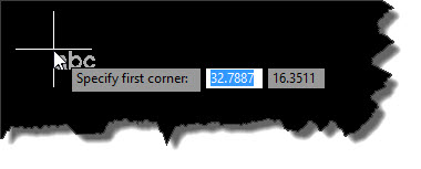
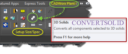
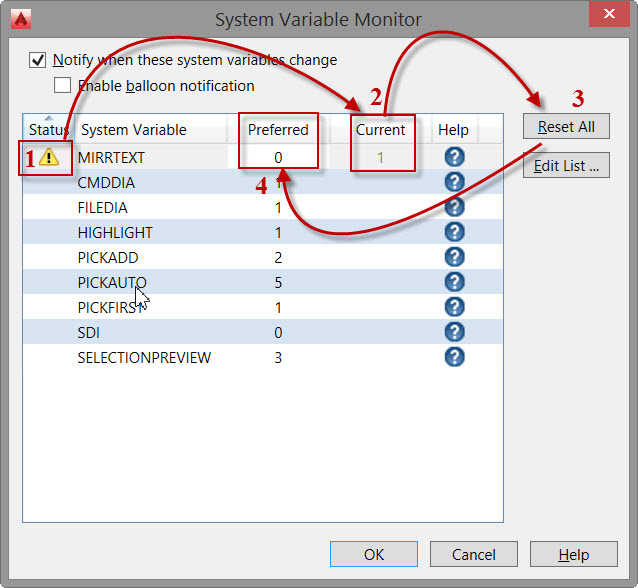
When you open a drawing that does have some AutoCAD variables that are different than what they normally are or how you’ve defined them to be, you will see a notification in the command line as shown below in image 1. To see what the variable is that has been changed and also give you a chance to reset the variable, use the command SYSVARMONITOR (image 2)

SYSVARMONITOR 1


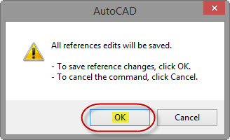
A dialog box will appear (as shown below).

  1. Shows the variable(s) in the list that are not set to their “Preferred” setting.
  2. Shows the current value to which the variable is set.
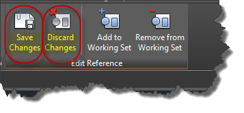
  3. Lets you quickly reset any variables in the list to the “preferred” values
  4. Displays what the “preferred” value is defined to be.

SYSVARMONITOR 2


You can add variables to this list as you see fit.

One variable that I like to have consistent is ATTDIA which controls whether a dialog appears when editing attributes. If this is turned off(which I can’t stand) the attribute prompts are shown in the command line only.

Shown below is how to add your variable to this list.
Note – you can also turn on a prompt so that if one of the variables changes, you will get a balloon-type of warning…

SYSVARMONITOR 5

Digging a little deeper about how these settings can get changed by one person and then when you open them on a different computer, these settings seem to stay with the drawing.

It is because some variables do stay with a drawing.

for example: when you are in the “OPTIONS” dialog box, when you see a yellow & blue .dwg icon next to a setting, these are variables that are saved in that drawing.

SYSVARMONITOR 3


Another place to easily check where a variable is saved is by using the System Variable Editor (SYSVDLG). Some variables are saved in the drawing or in the Registry or even not saved at all. This also a great place to see what the other values of a variable could be since not all variables are 1 or 0 (zero).

SYSVARMONITOR 4

Posted in Manage, New in 2016, TIPS | 3 Comments

Batch Convert DGN to DWG using Microstation

This tip requires that you (or someone else) has Microstation. To be honest, the only thing that I know how to do in Microstation is open a DGN file (Microstation file) and either  do a “Save as” > .DWG or use the batch processor that is within Microstation to convert a bunch of DGNs into DWG files.

Side Note: I wish that AutoCAD had some sort of batch utility that was built into the program like Microstation has. Notice in the screen shot below there is both a “Batch Converter” and a “Batch process”… (hint hint Autodesk)

  • Go to the “Utilities” menu and select “Batch Converter”

Picture1


Refer to the picture below to set the following:

  • What files are to be processed.
  • What file type you want the DGN to be convert to (in this case – “DWG”)
  • What folder the .DWG files should go into.

Picture_2


When the dialog box named “Save As DWG/DXF Options” opens – there are some Microstation settings that you will need to configure in order to get the desired results of your .DWG files – Like how Microstation handles references and attachments. And I think I remember someone saying that Microstation can have multiple Model Spaces…

Refer to the below Screen shot and adjust as you find necessary.

Picture3


Once the settings have been set, you can save these settings for future use if this will be an on-going process for a project.

Click the top button and then the bottom “Convert” button and watch it chug away…

Note: if you don’t get the desired results in the DWG files, you may need to adjust the settings in the above dialog. It might take some trial and error…

Picture4


I hope this helps or is at least a starting point for some of you.

~Greg

Posted in Manage, Modifying | Tagged | 1 Comment

Angular Dimensions More than 180° for ACAD 2016

Since the new DIMension command (which I love) has kind of changed the way we do dimensions, here is how you apply an angular degree that is more than 180°.

It has been about 5 years since I first posted about how to do this [here] so it is about time for an update.

Here’s how: TIP: READ THE COMMAND LINE!!!!!

  • Dim <enter>
  • Select “Angular”
  • Specify the  Vertex
  • Pick one end of a line
  • Pick the end of another line end
  • Pull away and place the dimension


Angle More Than 180

Posted in Dimensions, New in 2016, TIPS | Leave a comment

MTJIGSTRING

When you enter T <enter> at the command line, it starts the MTEXT command and you normally see “abc” prompt

Default MTJIGSTRING

When you enter MTJIGSTRING in the command line, you are able to enter ten characters to welcome you when you start typing MTEXT.

But luckily you can customize it (shown below)

MTJIGSTRING

Posted in Customization, New in 2016, Text | Leave a comment

Poll – Does your company use Annotative Text & Dimensions in model space.

Besides Civil 3D users, I know of no engineering firm that uses annotative text or dimensions in Model Space. I tend to teach people how to use it so that they know how. But I also teach them how to place text as dimensions in a layout tab since that is what I know most companies use and I don’t want the person to be thrown into a scenario where they don’t know how to do one or the other.

If you do answer “YES” Please explain how other disciplines (Structural. Electrical, mechanical) deal with your annotative text & Dims displaying in their model?

Posted in Uncategorized | 2 Comments

CADWorx Piping Displays As Single Line

Have you ever opened a CADWorx piping drawing only to find a bunch of center lines where your 3D piping should be? (shown below)

1 CADWorx Pipe displays one line

  • Use the CADWorx command CONVERTSOLID to make these single lines display correctly. This tool can also be found on the ribbon at: CADWorx Plant I tab > Setup Size/Spec panel > “3D Solids” tool” (Shown below).
  • Select the objects that you want to display correctly. I used ALL <enter>

2 CADWorx Pipe displays one line


After the tool does its magic, you should see the piping components displayed correctly.

One issue that I have noticed on a few drawings is that the next time I open the drawing, I have to run the command again…

3 CADWorx Pipe displays one line

Posted in CADWorx | 9 Comments

Add Objects to Block Using Edit Block In Place

If you were wondering, Yes there is a LISP routine to accomplish the same thing found [here] by Lee-Mac. But here is how you can do the same thing using the “Edit Block In-Place” option of editing blocks.

Sometimes it is nice to be able to draw objects  that will eventually be added to a block without having to draw them in the block editor. Shown below, there is a circle and line (green) that needs to be added to the block (cyan).

1 Block & Objects to be added


Here’s how:

Edit Block In Place

Here are the steps to add these objects to the block.

  • Select the Block
  • Right Click
  • Choose “Edit Block In-Place”

Note – if this option is greyed out then set the variable BLOCKEDITLOCK to <0> zero

2 Select Edit Block In Place


Verify the Block from the list and click OK.

Notice that editing a block in-place is using the REFEDIT command…

3 Select Block from List


Shown below is what the Block and its surrounding objects look like. The Block’s objects are shown normal while the surrounding objects are dimmed.

Once in the REFEDIT command, you can use the command REFSET which has an “Add” & “Remove” option. These options are easily accessible from the ribbon, Simply select the corresponding button to add or remove objects.

4 REFSET ADD & REMOVE


Once objects are added to he block, they are no longer faded.

5 Added objects appear brightOnce you are done adding or removing objects you can save these changes or discard them by using the buttons in the ribbon shown below.

6 Save or Discard Changes

You will be asked to verify the changes – Click OK

7 Verify changes


Now your edits have been saved you can see them in your block.


8 Objects have been added to block


Posted in Blocks, TIPS | 2 Comments