Import PDF Geometery

New in AutoCAD 2017 is the much-needed ability to import PDFs. This new feature will import geometry and True Type Fonts (.ttf) only. If your PDF file contains fonts that use an .shx font, that text will be imported as linework. But either way, this is by far my favorite new feature.

There are two options to import the PDF:
1) Importing a PDF by browsing to a file.
2) With a PDF already attached to the drawing (like an XREF) – Importing a portion of the PDF or the entire PDF.

Here’s how:

Browsing to a PDF:
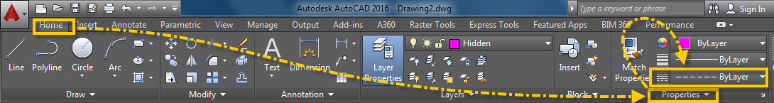
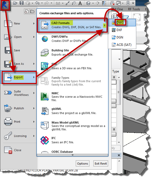
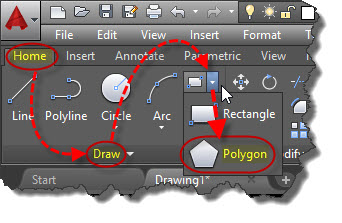
The Command to import a PDF is simply PDFIMPORT or the “PDF Import” button is found on the Insert tab > Import panel > Import Dropdown.

PDF Import

Notice the command line that asks you to “Select the PDF Underlay or [File]”. Click on the “File” option.
Select PDF or File

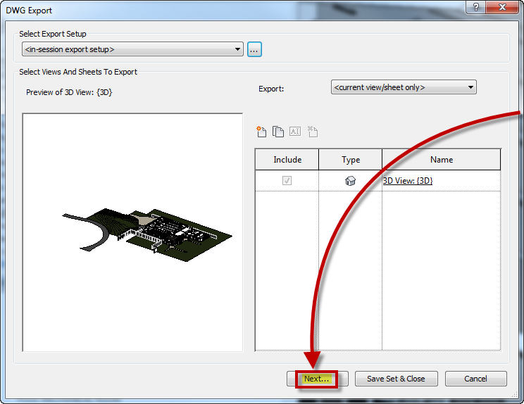
After you select the PDF, You will see the “Import PDF” dialog box.

Import PDF Dialog box

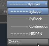
Make sure to check out the options in this dialog box. Something that I really like is that the line weights used in the PDF can be imported. The other great thing is that if the PDF was created using the option to create layers, those layers will be imported as well.

When you click on the “Options…” button of the dialog box, it will open the normal AutoCAD “Options” dialog box. Here you can specify where the PDF Import should place any Images that are in the PDF. These images will be imported and attached to the drawing like an XREF.

PDF Import Options Button

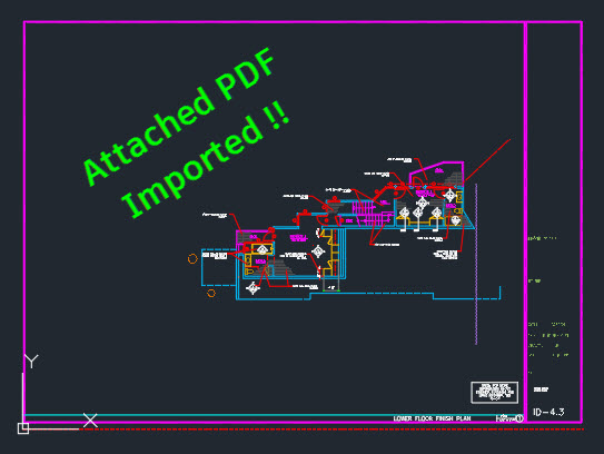
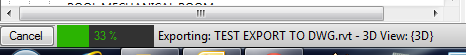
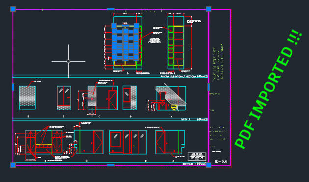
After you click the OK button back in the PDF Import dialog box, the progress bar will churn a little bit and then voila!!! your PDF is now imported as editable AutoCAD geometry.

PDF Import 1 Done

Importing an attached PDF:

You can use the PDFIMPORT command and button just like the above step.
Select PDF or FileThere is also a new button on the “PDF Underlay” Contextual ribbon that displays when you select the PDF that is currently in your drawing.

PDF Underlay Ribbon

When you start the command and select the PDF, you will see the options in the command line to select a portion of the PDF objects or All of the PDF.
Import all or someYou will then need to specify what should be done with the attached PDF after the import is completed.
Unload Detach or KeepThe Settings dialog box looks different but has the same settings as the “Import PDF” considering the PDF is already in your file.

Import PDF Dialog box

When you click OK it will churn away and your PDF will be imported.

Conversion Status

Attached PDF Imported

Advertisement
Posted in New in 2017, PDF, TIPS | 3 Comments

CAD Bloggers at Autodesk University

Once again I have been luck enough to attend Autodesk University. It is always a great time to meet fellow CAD nerds from around the world and especially catch up and meet fellow CAD bloggers. I thought it would be nice to show the bloggers that I have had the chance to catch up with this year. Hopefully some of your favorite bloggers are shown below.
P.S. – notice how many pictures are photo-bombed by R.K.

Lynn Allen
Twitter: @Lynn_Allen
Blog: lynn.blogs.com
Greg Lynn

Heidi Hewett
(my first AutoCAD Instructor)
Blog:
Heidi Greg

Shaan Hurley
Twitter: @ShaanHurley
Blog: http://autodesk.blogs.com/between_the_lines/Shaan Hurley

Melanie Stone-Perry & Frank Mayfield

Melanie
Twitter: @MistresDorkness
Blog: http://mistressofthedorkness.blogspot.com/

Frank
Twitter: @TheMadCadr
Frank and Melanie

Greg Battin
Twitter: @AutoCADTips1
Blog: autocadtips1.com
AutoCADTips1

Paul Munford
Twitter: @CadSetterOut
Blog: CadSetterOut.com
CSO

Donnie Gladfelter
Twitter: @thecadgeek
Blog: thecadgeek.com
The CAD Geek

Kean Walmsley
Twitter: @keanw
Blog: http://through-the-interface.typepad.com/
Kean

R.K. McSwain
Twitter: @cadpanacea
Blog: cadpanacea.com
RK McSwain

Kurt Moreno
Twitter: @wkfd
Blog: www.kungfudrafter.com
Kurt

Shaun Bryant
Twitter: @notjustcad
Blog: cadfmconsult.wordpress.com
Shaun Bryant

Patrick Hughes
Twitter: @Time_Trvlr
Website: www.cadtempo.com
Patrick Hughes

Owen Wengerd
Outside The Box
Website: otb.manusoft.com
Owen

Christopher Fugitt
Twitter: @C3DReminders
Blog: civilreminders.com
Chris Fugitt

Posted in Autodesk University | 9 Comments

Load A Linetype

Here is a simple explanation for how to load a linetype. I decided to demonstrate how to do so for an appropriate layer but a line type can be loaded from the “Properties” panel as well.

Here’s how:

  • In the Layer Dialog box, under the “Linetype” column, click on the linetype name that is set to your layer. In the example shown, it is set to “Continuous.”
  • A Dialog box “Select Linetype” will appear
  • Click the “Load” button
  • Another dialog box “Load or Reload Linetypes” will display. It is from this long list of linetypes that you need to select the specific linetype.
  • Click OK.
  • The linetype is loaded but it isn’t assign to the layer.
  • So now that you are back in the “Select Linetype” dialog box, select the newly loaded linetype and then click OK.
  • The linetype is now loaded in the drawing and assigned to a layer

Load Linetype for Layer

The loaded linetype can also be seen in the Properties palette and in the Properties panel of the ribbon on the Home tab of the ribbon.

Linetype in the Properties Panel 1

Linetype in the Properties Panel 2

Posted in Layers, Linetypes | 2 Comments

Revit Reorganize Revit Tabs

As I have been making my transition to Revit I have a few tips that you might find helpful even though there are plenty of other Revit blogs and resources to visit – I promise to keep this blog as AutoCAD-focused as possible but keep in mind that I am making the transition to Revit but my heart is truly in AutoCAD and these tips are for when you, as an AutoCAD user find yourself in the “World of Revit” and need some help.

I currently work for a structural engineering firm in Denver using Revit and occasional use AutoCAD. When I open Revit 2014 and newer, the various Revit “flavors” are all in one package. This package used to be called “Revit One Box” but that name faded away and it is simply called “Revit”.

When you open Revit in its default “out-of-the-box” settings the first panel of the ribbon is the Architectural tab – which is just fine if you are and Arch person. But for others like us Structural or MEP folks, it would be nice to be able to open Revit and have it open to the discipline in which we work. Thus the tips for today.

Simply Hold the CTRL button down and then drag the Ribbon tab to the front of the ribbon so that it opens when you open Revit. This also allows you to reorganize the other ribbon tabs that you have. Just be aware if your have many ad-ons, this could be messy, but worth it.

Structure Tab 1st baby

And to be honest, the lack of controls in Revit make me miss AutoCAD that much more everyday – like the CUI and customization… But Revit has its strengths in just doing what it does without having to need extra add-ons as much…

enjoy
~Greg

Posted in Customization, Revit | 7 Comments

Convert 3D Revit to DWG

Just in case you need to convert a 3D Revit model to 3D AutoCAD, here ya go. It is very simple but remember to click one button to make sure you work with ACAD solids…

Here is a snapshot of the Revit model:

3D view of Revit model

3D view of Revit model

With the Revit model open, Click the Application Menu (“Big R”) > “Export” > “CAD Formats” > Select “DWG“.

Revit 2 ACAD 2

In the “DWG Export” dialog box – Click on the ellipsis (button with 3 dots) to open the “Modify DWG/DXF Export Setup” dialog box.

  • Click the “Solids” tab
  • Select “ACIS solids
  • Click Next

Revit 2 ACAD 3

Click “Next…” to continue

Revit 2 ACAD 4

Define the folder where you would like the new DWG to reside and also give it a new name if desired. You can also define what DWG version to process it as. Click OK to proceed with the conversion.

Revit 2 ACAD 5

In the lower left of the Revit screen you will see a status bar showing you the progress of the conversion.

Revit 2 ACAD 6

Once it is done, notice the new DWG. I will warn you that the Revit File to DWG conversion will make the overall file larger. The Revit file used in this example was 58mb and after the conversion to DWG was 70mb.

Revit 2 ACAD 7

Now you can edit the converted file – Also note that the objects are AutoCAD solids.

Revit 2 ACAD 8

Posted in Revit | 6 Comments

Hurricane Batch Processor Review

AutoCAD batch scripts can be powerful by themselves, but if you couple that with the ability to apply them to a multitude of drawings then it can be really powerful. I first saw the power of scripting while using the “Core Console” in 2013 and made a post about it found here. But then realized that there was some limitations and one in particular was its inability to process OLE objects.

Script Pro is still pretty nice, but from my testing a batch processor called “Hurricane” I have grown fond of its built-in functions and scripts. There is a new version available called “Hurricane MX” but I have only used the older one which is just fine for me.

So I decided to try a batch of drawings using Hurricane and sharing the results with you.

Hurricane List of batch steps


A sneek peek into my “custom” script simply shows that the script loads a lisp routine (just to spice things up)

Script and LISP files


Shown below is the folder of drawings to be processed.

Hurricane 1


Shown below is the main interface of Hurricane. It is somewhat straight forward but takes time to get to learn just like everything. Specify the files (individual or entire folder)

Build the script in the ‘User Script” tab by selecting some pre-made scripts found in the “User Script List”. If you plan on selecting multiple pre-made scripts – DONT FORGET TO CHECK THE APPEND BUTTON.
Huricane 4


As shown below, the program builds a single script containing all of the steps that you define for the drawings that you selected to be processed.

NOTE – That you need to have a drawing currently open for the process to start. Just don’t have one of the drawings in the list of drawings that you are wanting to process open.

Hurricane 5


The results are shown below

Hurricane 6


And as a big relief – the drawing that contained an OLE object came out just fine.


Hurricane 7


Posted in Manage, OLE Objects, Scripts | Leave a comment

Tip: When Tracking Doesn’t Seem to Work

Here is one of the quirky things that AutoCAD does that might throw you for a loop. It involves “Tracking” whether it is “Object Snap Tracking” or “Polar Tracking” they seem to behave differently when Dynamic Input is turned onn or off. This is especially true for Object Snap Tracking. I have heard it said and taught, that these functions DO NOT work when Dynamic Input (DYN) is turned off. I am here to show you that they do.
When Dynamic Input is toggled on (as shown below) when you establish the reference point which has the green “glyph”, you pull away and see the dashed line and enter your tracking distance and you are just fine.

DYN Mode turned on OSNAP Tracking

DYN Mode turned on OSNAP Tracking

The trouble seems to be when Dynamic Input is turned off and you establish the same reference point. You see the green “glyph” and dashed line as you pull away, but when you enter the distance at the command line, the dashed line goes away making you think that you are unable to use Object Snap Tracking without DYN turned on.

The think that is happening is that the “focus” goes from the drawing area and then on to the command line. And don’t worry, it isn’t broke – all that you have to do is enter your distance AND PAUSE. Then re-establish the focus in the drawing area where you were by simply lining your cursor back into line where it was until you see the dashed line AND THEN HIT ENTER (shown below).

Object Snap Tracking Working without DYN turned on

Object Snap Tracking Working without DYN turned on

OTRACK Annoyance

The same can be said of using Polar Tracking. But it is easier to see that it works as opposed to using Object Snap Tracking. See if you can notice the difference below.

DYN turned on with Polar Tracking:

DYN turned on with Polar Tracking

DYN turned OFF with Polar Tracking:

DYN turned OFF using Polar Tracking

Posted in BASICS, Settling In, TIPS | 8 Comments

Shortcut Keys for AutoCAD, Inventor and Revit

Near the beginning of the year a blog post here showed the links to Autodesk’s AutoCAD for Microsoft Windows and Mac’s Shortcut keys (Aliases). They have now made available a list of shortcut keys to Autodesk Inventor and Revit. Below are the links:

~enjoy

Posted in BASICS, Revit, TIPS | Leave a comment

Using SUPERHATCH To Make Complicated Hatch Patterns

A very good question was asked in in the comments section of the following post about creating custom hatches [found here]. That post was about creating custom hatches using lines within a 1×1 square and then having the ability so save that custom hatch pattern to its own file and copying the contents into the bottom of your ACAD.PAT file that is located in your ACAD support path. The hatch pattern LISP routine was originally posted at Cadalyst.com 10 years ago and still works great (see why I like LISP so much) it can be [found here].

The question was basically – Why wont this routine work even though I am using nothing but lines and they all fit into the 1×1 square?

I was sent the file that had the linework and I had the same results.

Here is a snap shot of the desired hatch pattern.

Linework that needs to be new hatch pattern

During the SAVEHATCH portion of the routine it showed errors in the command line history of “invalid angles”…

Hatch Pattern Invalid Angle

So I tried changing UNITS and “Angle Type” but I still got this error and gave up on trying to figure that out.

Welcome to Express Tool SUPERHATCH!!!

First make a block of the objects that you want to define your hatch pattern.

Create A Block of the hatch shape

Then launch the SUPERHATCH command. Also found on the Express Tools tab > Draw panel > Super Hatch

SUPERHATCH on the ribbon

(Note: there are many options and ways of using this tool so I would suggest looking into the various options by hitting the F1 button after launching the tool)

Super Tip: One of my favorite uses of this tool is that you can make a hatch pattern out of curved objects!!!


There is also a great video by Lynn Allen demonstrating how to use SUPERHATCH and applying images as a hatch [found here]

Applying the Super Hatch

The prompts for using a block are shown above and are listed below:

  • Select “Block” from the Super Hatch menu
  • Select the block name from the “Super Hatch – Insert” dialog box and click “OK”

(The next few prompts are similar to inserting a block)

  • Specify an Insertion point:
  • Specify the X scale factor:
  • Specify the Y scale factor:
  • Specify the rotation angle:
  • Is the placement of this BLOCK acceptable? <Yes>
  • Specify block [Extents] First Corner <magenta rectang>:
  • Other corner:
  • Specify an option [Advanced options] <Internal point>: Pick inside of enclosed area to apply the hatch
  • hit Enter

Notice that after the hatch has been applied that it is now a “group” and not a true hatch. So if you decide to modify the boundary, it will not be “associative”

Posted in Customization, Express Tools, Hatch, TIPS | 1 Comment

Polygon Intro, Reminder and Cool Trick

Hopefully, today’s tip will help you AutoCAD “newbies” and you “old schoolers”
The POLYGON tool in AutoCAD creates “Simple Polygons” that are symmetrical.

The Polygon tool is located on the Home tab > Draw panel > next to the RECTANGLE tool there is a pull down arrow, under that list is the POLYGON tool.

POLYGON 1

  • Command line version: POLYGON <enter>
    Command Alias: POL <enter>

Method One: Making  a Polygon From a Center point – Out (like a circle)

  • Once the tool is launched, you are asked to “Enter the number of sides:” of the polygon
  • You are then asked to “Specify the center of the Polygon.” You can do this by simply picking a point in the drawing area.
  • Then you are asked if the polygon should be “Inscribed” or “Circumscribed“. This may be confusing for new users but it also trips up users that are “old pros” that have been using AutoCAD for a long time.
  • The last prompt is “Specify the radius of the circle:” which sounds confusing because it sounds like you are now creating a circle somehow…

Shown below are some examples that illustrate Polygons in relation to a circle. The circle and the Polygons share the same center point and the same radius. This illustration hopefully makes it easier to understand the prompts and which part of the polygon rests at the “radius” point. I also have to give the AutoCAD team kudos for adding a description after each option (Inscribed & Circumscribed) in newer releases of AutoCAD. It used to just ask you to specify an “I” for Inscribed or “C” for Circumscribed.

The arrow shown below that is labeled “Distance” shows the center point (back end of arrow) and the radius (at the arrow end).

Inscribed and Circumscribed with Shared

Inscribed & Circumscribed polygons with the same center point and the same radius

  • Inscribed:
    When you specify the radius of an inscribed polygon, you are defining where a corner of the polygon will be placed.

Inscribed

  • Circumscribed:
    When you specify the radius of a circumscribed polygon, you are defining where the midpoint of one of the edges or segments of the polygon will be placed.

Circumscribed


COOL TRICK

The “Cool Trick” that is mentioned in the title is something that is sometimes overlooked. It is an option that we glance over when the POLYGON command is launched. It is the “Edge” option. This is especially useful when creating a circumscribed polygon. Instead of specifying a center point and a radius, you define the length and angle of an “edge” of the polygon.

  • Define the Edge’s Angle & Length:
    Watch the Dynamic Input as the angle and length are entered to define the edge.

Polygon Egde define angle and length

  • Referenced Object:
    Shown below is simply an angled line with a distance and angle that I don’t know – but I want my polygon’s edge to be that length and at that angle Quickly

Polygon Edge 1


The Coolest trick is using the edge option to make a square. You simply tell it to make 4 sides – then pick 2 points and voila you have a square!!!

Polygon Edge Square

Posted in BASICS | Leave a comment