Use Align Space to Easily Align A Viewport View

Rotating a view within a viewport can be quite involved when using the DVIEW command as was shown in this post: https://autocadtips.wordpress.com/2013/06/03/dview-with-a-twist-rotating-a-viewport-view/

But as a guest named Nick pointed out, the ALIGNSPACE command from the Express Tools is a quick way in which rotating the view within a viewport to match that of a line in Paper Space is easy as using the ALIGN command.

It is really that easy too!!!

Align Space 1

Here’s how:

  • Make sure that you have a reference line in both model space and paper space.
  • Activate the viewport in which the view is to be rotated.
  • Start the ALIGNSPACE command. Found on the “Express Tools” tab > “Layout” panel > “Align Space” tool

Align Space 2

  • Pick 2 points within the viewport that define the angle
  • Pick 2 points in Paper space to define the desired angle
  • Click inside a viewport to apply the rotation to that viewport and then hit <enter>

Align Space 3

Note: The order in which you define the 2 points within the viewport and the order of the 2 points in paper space will be aligned accordingly.

Posted in Manage, Modifying, Paper Space, TIPS, Viewports | 14 Comments

Express Tool: EXPLAN – Improved PLAN command

The PLAN command is commonly used in 3D to get your view back to “home” and squared up so that you are looking down onto your drawing. It is also helpful when working in 2D drawings and the view has been rotated. Using PLAN will un-rotate your view back to “home.”
The EXPLAN command is an Express Tool and is a better version of the PLAN command (in my opinion). I usually tell CAD users to use PLAN to reset their view back to “home.” This works fine but the PLAN command does a ZOOM EXTENTS after the view has been adjusted. So the user has to navigate (zoom) back to where they were in the drawing prior to using the PLAN command.

With EXPLAN you can “square-up” your view based on an object that you select without doing a ZOOM EXTENTS.

Here’s how:

Shown below is a 3D view of an area of a drawing.

Explan 1


By using the usual PLAN <enter><enter> the result is a view that is perpendicular to the World UCS (WCS) but with a Zoom Extents applied to the result (shown below)

EXPLAN 2


On the other hand, Using the EXPLAN command found on the Express Tools tab > Tools panel > Extended Plan (shown below) asks you the same series of questions as the PLAN command but includes the ability to select an object.

Example:

  • EXPLAN
  • Select object – The view will be centered about the selected object.
  • <enter>
  • <enter>

EXPLAN 3


The result is shown below.

~enjoy

EXPLAN 4

Posted in 3D Intro, Express Tools, TIPS | 2 Comments

AutoLISP: Great Dialog Box to Turn On Layers from Various States

If you’re like me, you have a handful of routines, scripts or macros that let you basically “turn on” layers
Thaw those frozen layers; Unlock those locked layers; Turn on those Off layers…
The routine featured today combines all of those functions into one dialog box. The great thing about this routine is that it shows you only those layers that are currently Off, Frozen or Locked so that you don’t have the other layers that are turned on cluttering up your view. There is an optional function that lets you control these same layer states if they exist in an XREF. Simply check the box next to “Xrefs layers” for the ability to control these layers as well.

Here’s how:

  • Layer_On <enter> to start
  • Check the boxes under the “Properties” section that you would like to be turned “On”
  • Check the box next to “Xrefs Layers” to gain control over those layers as well

Select the layers under the “Layer List” section that you want to be turned “ON”. If all layers are needed to be selected, click the “Select all” button.

Layer On 1


This routine was provided by Stefan M. at the Autodesk forums. Please refer questions about the routine there: http://forums.autodesk.com/t5/Visual-LISP-AutoLISP-and-General/Thaw-layers-from-custom-dialogue-box/td-p/3944033/page/2


 ; Turn ON selected layers
 ; Stefan M. - 05.06.2013
 ; http://forums.autodesk.com/t5/Visual-LISP-AutoLISP-and-General/Thaw-layers-from-custom-dialogue-box/td-p/3944033/page/2
(defun C:LAYER_ON (/ *error* acDoc filen filew id l layers r prop var labels keys final l_name selected_layers)
  (vl-load-com)
  (setq acDoc (vla-get-activedocument (vlax-get-acad-object)))
  (vla-startundomark acDoc)

  (defun *error* (m)
    (and
      m
      (not (wcmatch (strcase m) "*CANCEL*,*QUIT*"))
      (princ (strcat "\nError: " m))
      )
    (vla-endundomark acDoc)
    )

  (defun remove_duplicates (lst)
    (if lst
      (if (vl-position (car lst) (cdr lst))
        (cons (car lst) (remove_duplicates (vl-remove (car lst) (cdr lst))))
        (cons (car lst) (remove_duplicates (cdr lst)))
        )
      )
    )

  (defun prompt_list ()
    (setq final (remove_duplicates (apply 'append (mapcar '(lambda (a b) (if (eq "1" a) b)) var l))))
    (if (eq "0" (last var))
      (setq final (vl-remove-if '(lambda (a) (wcmatch a "*|*")) final))
      )
    (if final (setq final (acad_strlsort final)))
    (start_list "a_list")
    (mapcar 'add_list final)
    (end_list)
    )

  (setq prop   '((LayerOn . 0) (Freeze . -1) (Lock . -1) (Plottable . 0))
        labels '("OFF Layers" "Frozen Layers" "Locked Layers" "UnPlottable Layers" "Xrefs Layers")
        keys   '("tog1" "tog2" "tog3" "tog4" "tog5")
        l      '(nil nil nil nil)
        )

  (vlax-for la (setq layers (vla-get-layers acDoc))
    (setq l (mapcar
              '(lambda (a b)
                 (if (= (vlax-get la (car a)) (cdr a))
                   (cons (vla-get-Name la) b)
                   b
                   )
                 )
              prop
              l
              )
          )
    )
  (setq l (reverse (cons (vl-remove-if '(lambda (a) (eq (strcase a) "DEFPOINTS")) (last l))
                         (cdr (reverse l))
                         )
                   )
        )

  (if (vl-some 'vl-consp l)
    (progn
      (setq filew (open (setq filen (strcat (getvar 'dwgprefix) "temp_layer_dialog.dcl")) "w"))
      (write-line
        "layer_on_dialog : dialog { label = \"SELECT LAYERS\";
       : row {
       : list_box { label = \"Layer List\"; key = \"a_list\"; width = 30; height = 15; multiple_select = true; allow_accept = true;}
       : column {
       : boxed_column { label = \"Properties\"; fixed_height = true;  alignment = top;"
        filew
        )
      (mapcar
        '(lambda (a b c)
           (if c
             (write-line (strcat "       : toggle { label = \"" a "\";    key = \"" b "\"; }") filew)
             )
           )
        labels keys (append l '(T))
        )
      (write-line "       }: button { label = \"Select all\"; key = \"selall\"; alignment = bottom;}
       }}ok_cancel;}" filew)
      (close filew)

      (if
        (>= (setq id (load_dialog filen)) 0)
         (if
           (new_dialog "layer_on_dialog" id)
            (progn
              (setq var (subst "0" nil (read (cond ((getenv "layer_dialog_box_settings")) ("(\"1\" \"0\" \"0\" \"0\" \"0\")")))))
              (prompt_list)
              (action_tile "a_list" "(setq selected_layers $value)")
              (action_tile "selall" "(set_tile \"a_list\" (setq selected_layers (apply 'strcat (mapcar '(lambda (a) (strcat (itoa (vl-position a final)) \" \")) final))))")
              (mapcar
                '(lambda (a b)
                   (if b
                     (progn
                       (action_tile
                         a
                         "(setq var (mapcar 'get_tile keys) selected_layers nil) (set_tile \"a_list\" \"\") (prompt_list)"
                         )
                       (set_tile a (nth (vl-position a keys) var))
                       )
                     )
                   nil
                   )
                keys
                (append l '(T))
                )
              (setq r (start_dialog))
              (unload_dialog id)
              (if var
                (setenv "layer_dialog_box_settings" (vl-prin1-to-string var))
                )
              )
            (princ "\nWrong dialog definition")
            )
         (princ "\nDCL file not found")
         )
      (if (findfile filen) (vl-file-delete filen))
      (if
        (and (= r 1) selected_layers)
        (progn
          (foreach x (read (strcat "(" selected_layers ")"))
            (mapcar
              (function
                (lambda (a b c)
                  (if
                    (and
                      (eq "1" c)
                      (vl-position (setq l_name (nth x final)) a)
                      )
                    (vlax-put (vla-item layers l_name) (car b) (- (1+ (cdr b))))
                    )
                  )
                )
              l
              prop
              var
              )
            )
          (if
            (or
              (eq (nth 1 var) "1")
              (eq (nth 2 var) "1")
            )
            (vla-regen acDoc acActiveViewport)
          )
        )
      )
    )
    (princ "\nAll layers are on and plottable.")
    )
  (*error* nil)
  (princ)
  )
Posted in AutoLISP, AutoLISP XREFs, AutoLISP: Manage, AutoLISP: Modify, Layers | 1 Comment

AutoLISP: Purge Missing SHX files

If you have drawings that are constantly missing SHX (shape) files, the routine posted below is now your friend.

The routine was posted in the LISP forum at CADTutor at the following link. Please refer questions there.
http://www.cadtutor.net/forum/showthread.php?37306-remove-unknown-SHX-files&highlight=delete+shape+files

Here’s how:

  • PSHX <enter>

The result in the command line will show how many unresolved shape files were removed from the drawing.

Missing SHX 1 Missing SHX2Thanks for sharing this routine Kheylan


;; posted by: Kheylan
;; Downloaded from CADTutor forum
;; http://www.cadtutor.net/forum/showthread.php?37306-remove-unknown-SHX-files&highlight=delete+shape+files

(defun C:PSHX ()

  (vl-load-com)
  (vlax-for item
         (vla-get-textstyles
           (vla-get-ActiveDocument (vlax-get-acad-object))
         )
    (if
      (not
    (vl-filename-extension (setq fname (vla-get-fontfile item)))
      )
       (setq fname (strcat fname ".shx"))
    )
    (cond ((findfile fname) nil)
      ((findfile (strcat (getenv "WINDIR") "\\FONTS\\" fname))
       nil
      )
      (t
       (vla-put-fontfile item "ltypeshp.shx")
       (princ "\nChange ")
       (princ fname)
       (princ " on ltypeshp.shx")
      )
    )
  )
  (princ)
)
;(princ "\nPurge unreferenced shape files, Lisp Command : PSHX")
Posted in AutoLISP, AutoLISP: Manage, Linetypes, Manage | 3 Comments

DVIEW with a Twist: Rotating a Viewport View

DviewWithTwist

Not everything that we draft or model in AutoCAD is at 90 degree increments. For this reason when we want to make our model aligned with the sheet of paper.

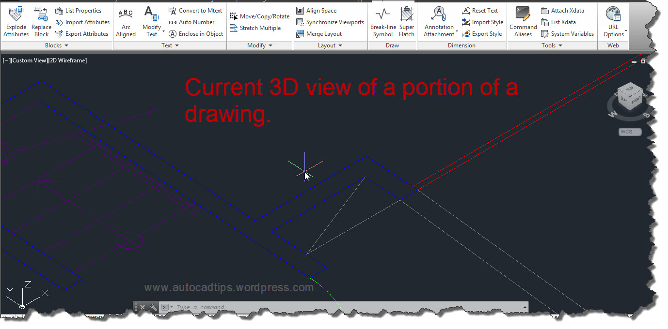
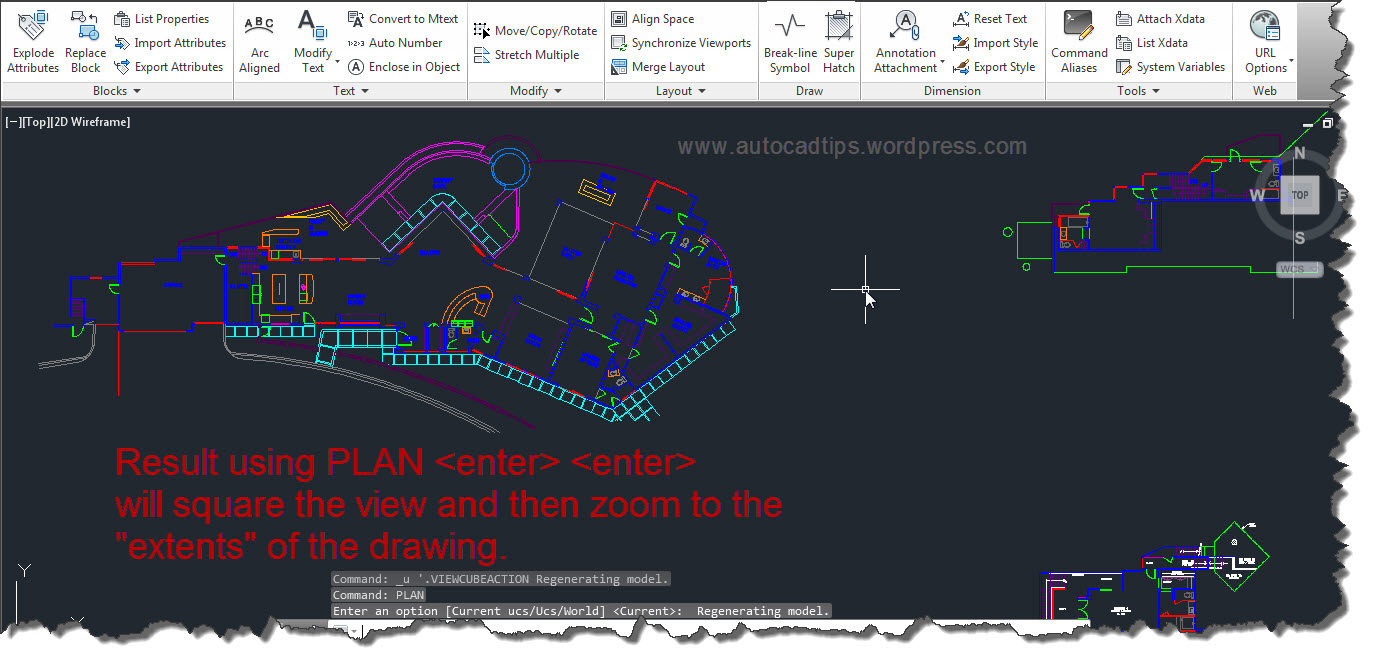
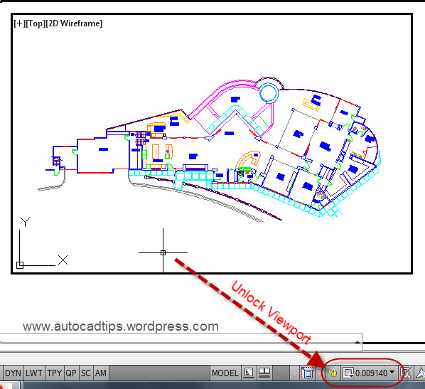
Shown below is a house that has 2 major axis. One axis happens to be aligned on the zero degree axis and the other is not. And it so happens that the portion that is not aligned to zero needs to have a viewport aligned to it and dimension applied to it.

Side Note: A simple approach that might be applicable can be found here: VPROTATEASSOC. This method rotates the entire viewport and the view of objects shown in the viewport.

DVIEW1


The method of rotating the view within a viewport that is described in this post is called “DVIEW with a Twist”. And it should be noted that this does not rotate any objects thus modifying any of the objects. It merely rotates the view of the objects.

Before we begin, you will need to find out the angle that the view will be rotated by. We will need to do this seperately because there is not an option for a reference like there is in the Rotate command (shown here)

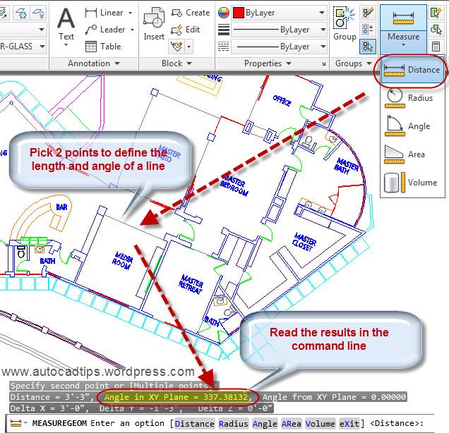
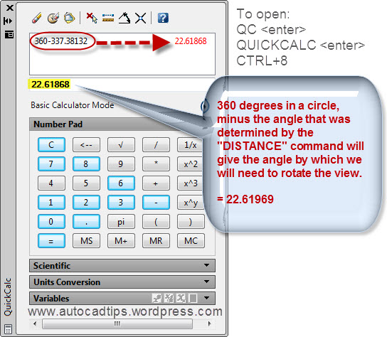
To find out the angle of the existing objects, use either the LIST or DISTANCE (aliases: LIST = LI, DISTANCE = DI) command on an objects that represents the desired angle. In the picture shown below, I used the DISTANCE command and picked 2 points. Then I noted the angle that is shown in the command line.

DVIEW2-A


Open the Quick Calculator by using any of the following:

  • QC <enter>
  • QUICKCALC <enter>
  • CTRL + 8

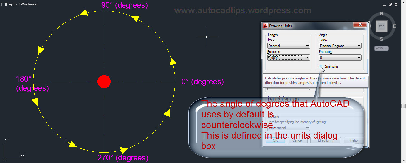
Because the view needs to be rotated is in the positive direction (counter-clockwise), the angle that was noted from the “Distance” command will be subtracted from 360.

Copy this total to your clipboard by highlighting it and then right click > copy


DVIEW4

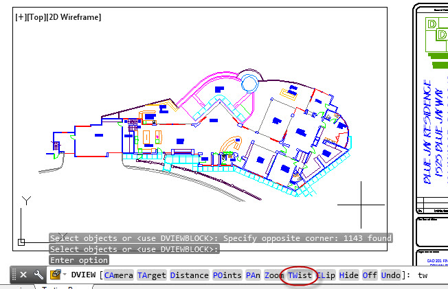
We can now start the DVIEW command

Before you launch the DVIEW command, activate the viewport and make sure that the viewport is unlocked (shown below)

DVIEW2


  • DVIEW <enter>

DVIEW6

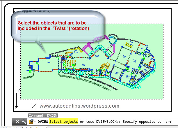
  • Select objects that are to be included in the “Twist” operation by using a window or crossing selection.
  • hit <enter> when finished selecting objects

DVIEW5


  • Specify the angle to rotate the view. If you know the angle enter it in the command line. If you used the QuickCalc and copied it to the clipboard, simple paste it into the command line and hit enter.

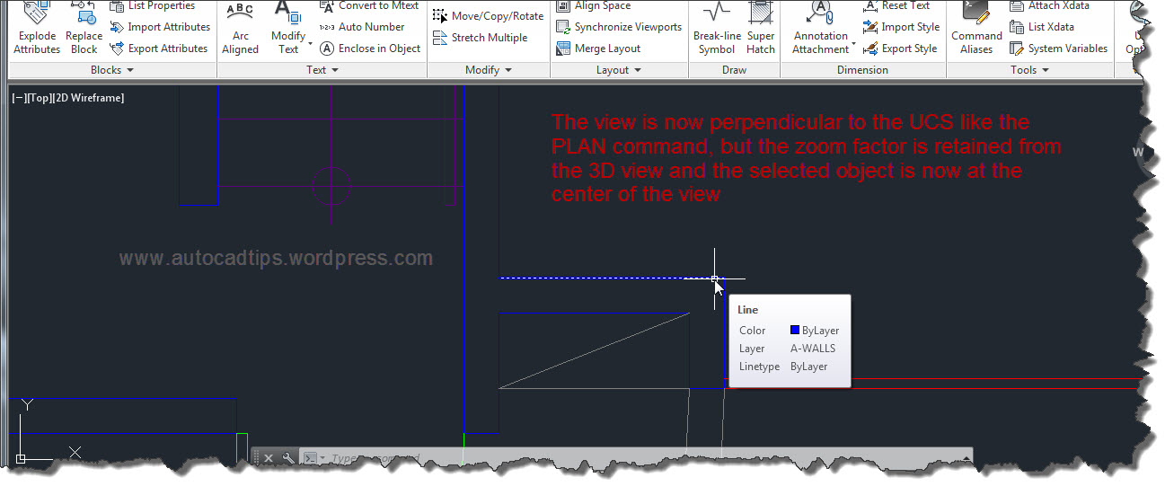
Note that the center point of rotation is located at the center of the viewport, not the center of the objects selected.

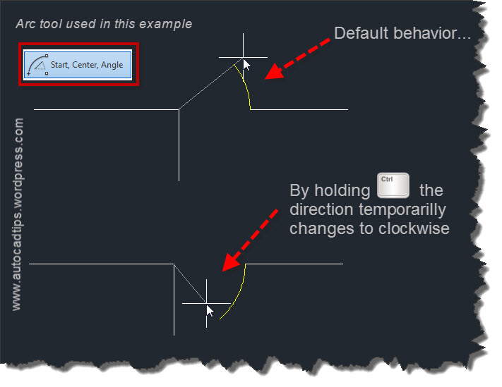
Also note: If the angle of rotation needs to be a clockwise rotation, you simply apply a minus sign in front of the angle. Ex. -45 will rotate the view in the clockwise rotation 45 degrees.

DVIEW7


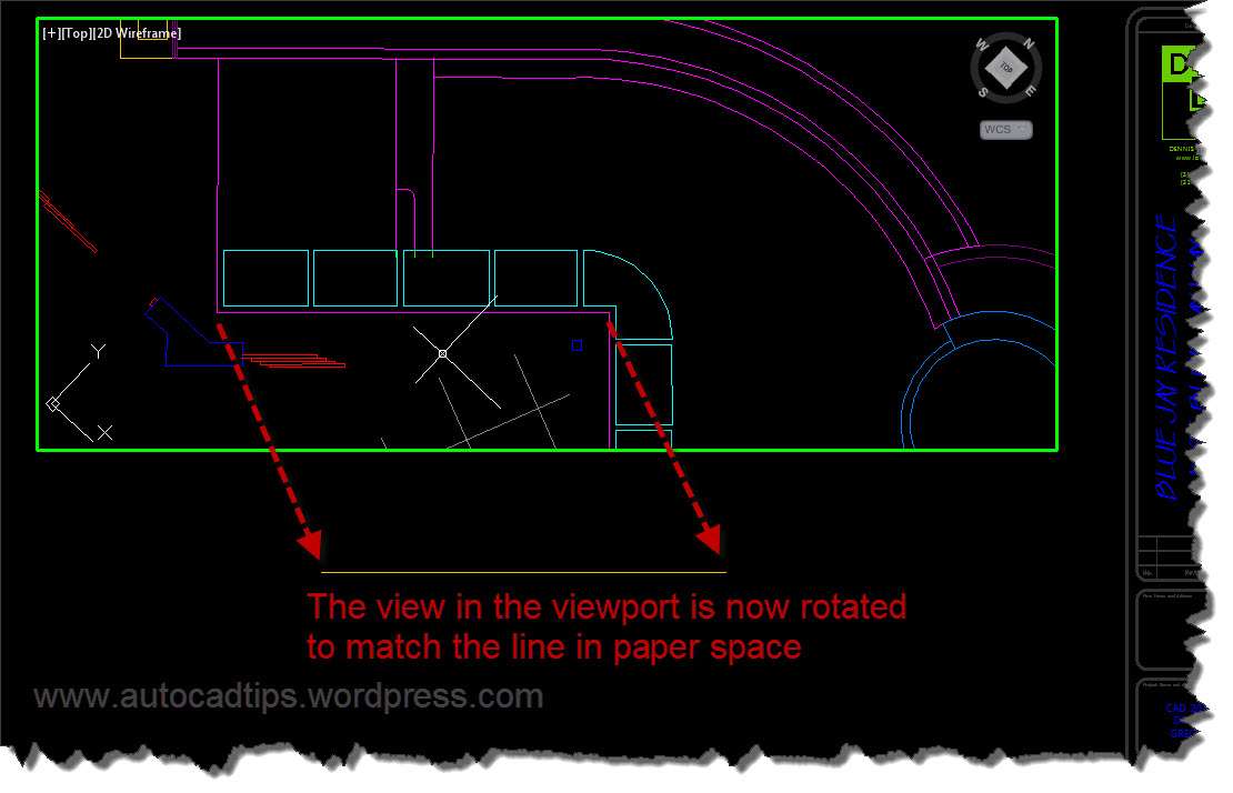
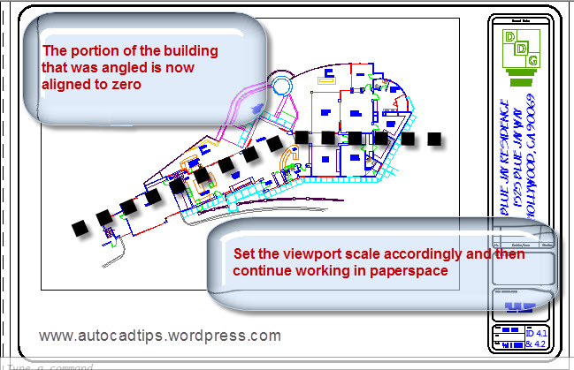
The portion of the building that was earlier at an odd angle is now lined up at zero degrees. You can now center that portion of the building in the viewport and set the viewport scale to begin placing dimensions and text in paperspace.

DVIEW8

Posted in BASICS, Dimensions, Layout, Modifying, Paper Space, TIPS | 12 Comments

AutoLISP: Purge Page Setups

The code posted below will purge all Page Setups except for the current page setup (if one is applied).
If you have ever received a drawing with many page setups this routine will help reduce the amount of setups that you have to navigate.

Here’s how:
DEL_PAGESETUPS
~enjoy


;;  Function to delete all user plot set ups
;; Posted by; CAB @ http://forums.augi.com/showthread.php?63099-page-setup-import-vlisp
(defun c:Del_Pagesetups (/ curdwg pslayout x) 
  (vl-load-com) 
  (setq 
    curdwg   (vla-get-ActiveDocument (vlax-get-Acad-Object)) 
    pslayout (vla-get-Layout (vla-get-PaperSpace curdwg)) 
  ) ;_ end of setq 
  ;; Call RefreshPlotDeviceInfo before GetPlotDeviceNames 
  (vla-RefreshPlotDeviceInfo pslayout) 
  (vlax-for x (vla-get-Plotconfigurations curdwg) 
    (vla-delete x) 
  ) ;_ end of vlax-for 
)               ; End Plot_config_list 
Posted in AutoLISP, AutoLISP: Manage, AutoLISP: Modify, Manage, Printing - Plotting, Uncategorized | 3 Comments

AutoLISP: Advanced Polyline Offset

Not knowing what to call this routine, I think that it is more of a combination of an advanced Offset command that automates the placement of the vertices at the (M2P) Mid-Between-2-Points.

If you need an offset that is between 2 polylines and the 2 polylines are not truly parallel to each other, the result of the polyline might not be the desired result.

OffsetPL2Mid 1

This process is automated by using this routine written by Alan Thompson and found at CADTutor: http://www.cadtutor.net/forum/showthread.php?73308-Multiple-Offsets&p=535978&viewfull=1#post535978

(Please refer questions or requests to the forum where the lisp routine was originally posted)

OffsetPL2Mid 2

Note: that the output offers an option for the created polyline (LWPolyline or Polyline)

OffsetPL2Mid 3

As an added bonus, the routine handles polylines that are at different elevations (z values) and it even handles 3DPolylines pretty well.

OffsetPL2Mid 4

OffsetPL2Mid 5

Thanks Alan!!

Here’s how:

  • LBL <enter> to start
  • Select the 1st polyline
  • Select the 2nd polyline
  • Specify the output polyline (LWPoline or Polyline)
  • RE <enter> or REGEN <enter> to get rid of the temporary dashed red lines


(defun c:LBL (/ foo AT:GetSel _pnts _pline _lwpline _dist e1 e2)
  ;; Draw (LW)Polyline between two selected curves (at midpoint of vertices).
  ;; Alan J. Thompson, 09.29.10
  ;; http://www.cadtutor.net/forum/showthread.php?73308-Multiple-Offsets&p=535978&viewfull=1#post535978
  (vl-load-com)

  (defun foo (e)
    (and (wcmatch (cdr (assoc 0 (entget (car e)))) "LINE,*POLYLINE,SPLINE")
         (not (vlax-curve-isClosed (car e)))
    )
  )

  (defun AT:GetSel (meth msg fnc / ent)
    ;; meth - selection method (entsel, nentsel, nentselp)
    ;; msg - message to display (nil for default)
    ;; fnc - optional function to apply to selected object
    ;; Ex: (AT:GetSel entsel "\nSelect arc: " (lambda (x) (eq (cdr (assoc 0 (entget (car x)))) "ARC")))
    ;; Alan J. Thompson, 05.25.10
    (while
      (progn (setvar 'ERRNO 0)
             (setq ent (meth (cond (msg)
                                   ("\nSelect object: ")
                             )
                       )
             )
             (cond ((eq (getvar 'ERRNO) 7) (princ "\nMissed, try again."))
                   ((eq (type (car ent)) 'ENAME)
                    (if (and fnc (not (fnc ent)))
                      (princ "\nInvalid object!")
                    )
                   )
             )
      )
    )
    ent
  )

  (defun _pnts (e / p l)
    (if e
      (cond ((wcmatch (cdr (assoc 0 (entget e))) "ARC,LINE,SPLINE")
             (list (vlax-curve-getStartPoint e) (vlax-curve-getEndPoint e))
            )
            ((wcmatch (cdr (assoc 0 (entget e))) "*POLYLINE")
             (repeat (setq p (1+ (fix (vlax-curve-getEndParam e))))
               (setq l (cons (vlax-curve-getPointAtParam e (setq p (1- p))) l))
             )
            )
      )
    )
  )

  (defun _pline (lst)
    (if (and (> (length lst) 1)
             (entmakex '((0 . "POLYLINE") (10 0. 0. 0.) (70 . 8)))
             (foreach x lst (entmakex (list '(0 . "VERTEX") (cons 10 x) '(70 . 32))))
        )
      (cdr (assoc 330 (entget (entmakex '((0 . "SEQEND"))))))
    )
  )

  (defun _lwpline (lst)
    (if (> (length lst) 1)
      (entmakex (append
                  (list '(0 . "LWPOLYLINE")
                        '(100 . "AcDbEntity")
                        '(100 . "AcDbPolyline")
                        (cons 90 (length lst))
                        (cons 70 (* (getvar 'plinegen) 128))
                  )
                  (mapcar (function (lambda (p) (list 10 (car p) (cadr p)))) lst)
                )
      )
    )
  )

  (defun _dist (a b) (distance (list (car a) (cadr a)) (list (car b) (cadr b))))

  (if
    (and
      (setq e1 (_pnts (car (AT:GetSel entsel "\nSelect first open curve: " foo))))
      (setq e2 (_pnts (car (AT:GetSel entsel "\nSelect next open curve: " foo))))
      (not (initget 0 "Lwpolyline Polyline"))
      (setq *LBL:Opt* (cond ((getkword (strcat "\nSpecify line to draw: [Lwpolyline/Polyline] <"
                                               (cond (*LBL:Opt*)
                                                     ((setq *LBL:Opt* "Lwpolyline"))
                                               )
                                               ">: "
                                       )
                             )
                            )
                            (*LBL:Opt*)
                      )
      )
    )
     ((if (eq *LBL:Opt* "Lwpolyline")
        _lwpline
        _pline
      )
       (vl-remove nil
                  (mapcar (function (lambda (a b)
                                      (if (and a b (not (grdraw (trans a 0 1) (trans b 0 1) 1 1)))
                                        (mapcar (function (lambda (a b) (/ (+ a b) 2.))) a b)
                                      )
                                    )
                          )
                          e1
                          (if (< (_dist (car e1) (car e2))
                                 (_dist (car e1) (last e2))
                              )
                            e2
                            (reverse e2)
                          )
                  )
       )
     )
  )
  (princ)
)
Posted in AutoLISP, AutoLISP: Creating, AutoLISP: Modify, AutoLISP: Polylines | 4 Comments

AutoCAD 2014 Self Intersecting Polylines

With AutoCAD 2014 you now have the ability to use the FILLET or CHAMFER commands on a polyline that is “self-intersecting.” When the “radius” of a FILLET is set to <0> or when there is no angle set to a CHAMFER, these tools can be used to clean intersections by trimming or extending objects at their intersections. But since a polyline is a single object, this hasn’t been possible without the help of an add-on like a lisp routine or .NET application.

Here are a few posts that describe how to do use FILLET or CHAMFER to clean intersections:

https://autocadtips.wordpress.com/2011/08/14/fillet-radius-set-to-zero/

https://autocadtips.wordpress.com/2012/09/04/add-a-fillet-or-chamfer-with-no-trim/

The great thing is that there is no change to how the FILLET or CHAMFER command works to use this new ability. Simply use the FILLET or CHAMFER command as normal and the ability to select 2 different segments of a polyline are now available.

Polyline Self Intersection 2

Below is an example of how AutoCAD 2013 did not have this feature:

Polyline Self Intersection 1

Polyline Self Intersection 3

Posted in Modifying, New in 2014 | 5 Comments

AutoCAD 2014 Merge Layers from the Layer Properties Manager

This new feature is cool in many ways but one reason why is that I remember reading somewhere like the Augi wish list (http://www.augi.com/wishlist) or even on twitter that Jimmy B from http://www.jtbworld.com/ simply wished that he could easily select the layers from the Layer Proprieties manager and tell them to merge into another layer. And the next thing you know, that same feature shows up in AutoCAD 2014. So it is cool to know that Autodesk listens.

This new feature is really as simply as described above.

Open the Layer properties manager: LA <enter>

Layer Merge 1A


You can select a single layer or multiple layers. To select multiple layers use the normal multiple selection method either with the CTRL button or Shift button

Once the Layers are selected, right Click

Select “merge selected layer(s) to…”

Select the a layer from the pop-up box. These are layers that were not included in the selection of layers that you previously made because these are the “destination” layers. If you do not see your destination layer in this list, it is most likely because it was included in the selection of layers. So you will need to back up a little and re-select your layers. This time DON’T include the destination layer in the selection set.

Once you have selected a destination layer from the “Merge to Layer” dialog box, click OK

Then verify that the layer will be merged to the specified layer and click “Yes”

Merge Layers 1


The result is that the Layers and all of their objects have been merged into the layer that you specified and the old layers have been purged from the drawing.

Merge Layers 2


Posted in BASICS, Layers, New in 2014 | 12 Comments

AutoCAD 2014 Arc Improvement

With AutoCAD 2014, the ARC command has a simple-but-needed improvement. By default in AutoCAD, arcs are created counter clockwise. With 2014 you can control the creation of arcs to be clockwise or counter clockwise by simply holding the CTRL button.

See below for a more detailed look:

Simply opening the Arc tool’s flyout, there isn’t any obvious, visible change.


2014 Arc feature1


The direction that arcs are created are controlled in the UNITS dialog box

2014 Arc feature2


Although the new ARC direction option is available in all of the various arc tools, the most practical and obvious uses of the new ARC direction option are found in the ARC options shown below.

2014 Arc feature3


In the picture below, the upper arc that is being created shows the default ARC direction. The lower arc shows the new ARC direction option by hold the CTRL button during the command

2014 Arc Feature4

Posted in BASICS, New in 2014, TIPS | 4 Comments