
This post isn’t a fix-all solution but it has helped printing/plotting issues that I’ve recently encountered. There are some helpful AutoCAD variables and an adjustment to your preferred “Visual style(s)” that can help make printing 3D solids look correct in your print.
First – The issue that we encountered was that intersecting solids didn’t have a clear intersection in the print and curved 3D objects were displaying lines where a “tessellation” of the curves would be.

The settings of the visual styles for a viewport can be confusing. Note that there is a difference of a “Visual Style” and “Shade Plot” setting. This trips me up a lot and I confuse them for each other…
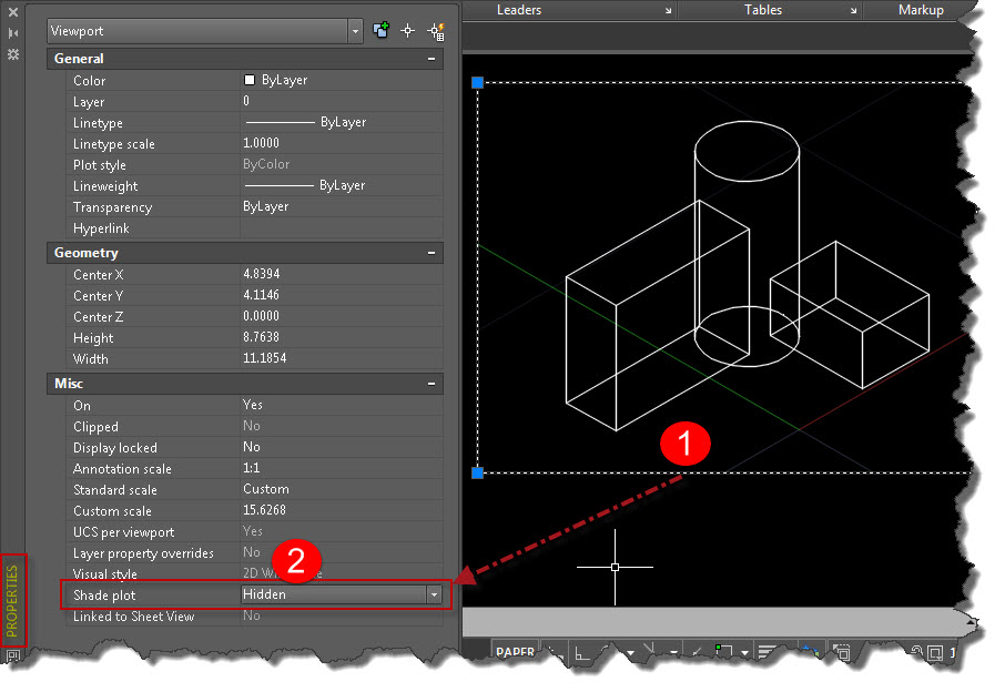
For the purposes of this blog post, I will keep it simple and keep the visual style of the Viewport set to “2D Wireframe” (shown below)

- Then change the “Shade Plot” setting of the viewport by selecting the edge of the viewport from paper space and opening the “Properties” palette. (right-click > Properties)
- Change “Shade Plot” from “As Displayed” to “Hidden”
Change the Visual Style to not display the “Isolines”
Use the command VISUALSTYLES in the command line to open the Visual Styles palette.
- Select the Visual Style that you wish to change in the upper section of the palette. In this example, I changed the “Hidden” Visual Style.
- Scroll down in the palette to the “Edge Settings” section, Change the property called “Show” from “Facet Edges” to “Isolines“
- Change the “Number of Lines” setting from “20” to “0” (zero).

In addition to making this change to the Vistual Style, changing the following AutoCAD variables helps the plot to display correctly.
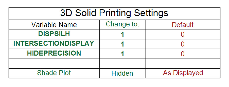
The result is shown below. Hopefully you find this useful.


Good morning Greg,
In this case, I’ve a question.
How to completely hide the lines or silhouettes on the bends or elbows of a pipelines.
I means, the pipelines is only consists of two parallel lines along each edges of the pipes.
Again, thank you in advance.
Best regards,
Wisnu
NB:
In order to minimize the number of lines in a 3d construction, should I, also change the isolines to 1..?
Hi Greg,
I’ve another question….
When i assign a visual style to a viewport (like “realistic”) the 2d texts, hatches, lines and polylines under the 3D dolids (i have them as a base) decreases very much the quality.
And overall the printing files are HUGE….. so i can print such file only by passing through a PDF.
Do you have some advice on handle with visual styles and print??
This is the answer I have been searching for for many years.. I don’t know how much time I’ve wasted redrawing viewports because I didn’t know this.. Thank you so much!
Awesome!!
I’m glad it helped
~Greg
Great! This solved my Pdf printing problem.
Thank you Greg.
Awesome! I’m glad it helped
~Greg
Hello Greg,
I’m in a bit of a pickle here. I can’t seem to resolve a layout matter. When I print a pdf of a viewport, containinga 3D drawing, it appears as raster image (not a vector). Are there any settings to resolve the matter? I am using Autocad 2016.
Cheers,
Bogi
Hey Bogi,
It sounds like you are using the model documentation feature to document the 3D objects – is that correct?
The model documentation (VIEWBASE command) seems to have been added to AutoCAD but not fixed so that people can use it in industry. There are many issues with it such that it causes more issues to use it instead of using regular view ports.
If you are using regular viewports and are still getting issues, send me a file so that I can look at it and also include what type of printer you are printing to or what PDF virtual printer is being used.
Thanks,
~Greg
greg.battin@gmail.com
Hello Greg,
When i try print 3d shade object 2d text like a blur but when i am that 3d object wire frame everything ok , but i need 3d object with shade can u help me about this problem thanks
Hi Greg, i have created a 3D model and then used the view base command to create 2D views of the model in a 3rd angle projection, i have kept one viewport in the top right of my drawing which has the 3D model. however when i try and plot the drawing the 2D views created from the viewbase command do not show up or plot, the dimensions and details from the 2D views plot fine…. this is driving me insane!
Thanks
George
(Apprentice project mechanical engineer)
Hello, I am super excited about the settings here, they are exactly what I needed to display my 3D prints the way I want them. The only downside to this is that after making these adjustments I seem to have lost my ability to print with Transparent 3D solids.
https://autocadtips.files.wordpress.com/2011/03/trans4.jpg
Make sure that this setting is checked when you plot with transparency
Hi, I checked that and it does not work.
Hello,
This is helpful, thank you. Does this only work for 3D solids? I have converted my 3d pipe to a mesh so it is stretchable within a dynamic block. Can I make this mesh appear without tessellation when I print?
Thank you
I never use mesh objects so I don’t know.
Thank you that fixed dark edge problem.
I changed the setting to draw a true silhouette in the 2d wire frame visual style.
Sir, I want to buy you a beer! Your post is worth of GOLD.
Thank you very much,
Your detail steps helped me greatly in solving my problem.
again, Thank you very much sir, whoever wrote this.
You’re Welcome. I am happy that the tip helped.
~Greg
This is the answer I have been searching for for many days. I don’t know how much time I’ve wasted redrawing viewports because I didn’t know this.. Thank you so much!
Hi Greg,
It works, but the silhouette edges of my cilinders/free standing columns are not showed, they are faded?
this is great, i’ve been doing solprof just to achieve vector lines but doing this save a lot of time. also, do you have any idea on how to shade plot conceptual but vectorize?. thanks.